background image

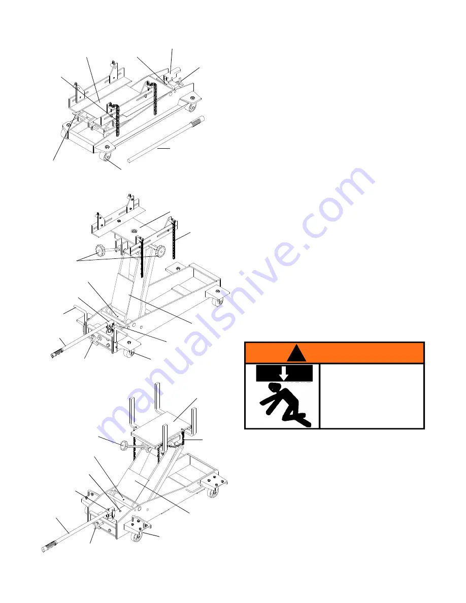
Release Valve Knob

Saddle

Tilt Adjustment

Knob

Position

 Handle

Oil Filler Plug
(not shown)

Caster

Pump Handle

Chain

Handle Sleeve

Lift Arm

Grease Fitting Nipple

Release Valve Knob

Saddle

Tilt Adjustment Knob

Oil Filler Screw

Caster

Pump Handle

Chain

Handle Sleeve

Lift Arm

3

ASSEMBLY

Little or no assembly is required. Refer to Figures in
the manual for details in understanding the assembly
and the components of your product.

OPERATION

Raise saddle:

1. Locate and close release valve by turning knob
    clockwise firmly, then pump the pump handle until
    the load is contacted.
2. Follow vehicle manufacturers recommended proce-
    dures for removing the load as outlined in vehicle
    service manual or repair guide.
3. Secure load with provided chains. Ensure load's
    center of gravity is centered on the saddle and load
    is stable before moving jack.

Lower saddle:

Caution! 

Be sure all tools and personnel are clear

before lowering load. Dynamic shock loads are created
by quickly opening and closing the release valve as the
load is being lowered. The resulting overload may
cause hydraulic system failure.

1. Slowly, gently turn the release valve knob
    counterclockwise, 

never more than 1/2 full turn

until the load is completely lowered.

2. Immediately transfer the load to an appropriate
    repair fixture.

Figure 1 - Model 41100 Components

41100-M0

Release Valve

Knob

Saddle

Tilt Adjustment

Knob

Oil Filler Plug
(not shown)

Caster

Pump Handle

Chain

Handle Sleeve

Figure 2 - Model 42000 Components

Figure 3 - Model 43000 Components

Grease Fitting Nipple

To avoid crushing and related
injuries:
NEVER work on, under or
around a load supported only
by a jack. Immediately
transfer the load to an
appropriate work station.

!

  WARNING

Summary of Contents for 41100

Page 1: ...000 Capacity 1100 lb 2000 lb 3000 lb Model 42000 Hydraulic Transmission Jacks Printed in Taiwan Operating Instructions Parts Manual Model 43000 SFA Companies 2005 10939 N Pomona Avenue Kansas City MO...

Page 2: ...Manuals are available from manufacturer see Replacement Parts pages 4 thru 7 PRODUCT DESCRIPTION Omega Hydraulic Transmission Jacks are designed to be used as an aid in the removal and installation o...

Page 3: ...ad s center of gravity is centered on the saddle and load is stable before moving jack Lower saddle Caution Be sure all tools and personnel are clear before lowering load Dynamic shock loads are creat...

Page 4: ...e moving parts Symptom TROUBLESHOOTING MAINTENANCE Important Use only a good grade hydraulic jack oil Avoid mixing different types of fluid and NEVER use brake fluid turbine oil transmission fluid mot...

Page 5: ...451 6 6200 108 Chain 2 4 450 3 5000 100 Saddle Assembly 1 5 450 4 5300 108 Angle Bar 2 6 450 3 5700 108 Tilt Screw 1 7 450 3 5600 205 Saddle Holder 1 8 G89 0 9003 7002 Caster Assembly 4 9 450 6 4409 1...

Page 6: ...ilt Screw 1 7 G52 6 4401 103 Tilt Screw 1 8 G52 6 1709 106 Tilt Knob 2 9 G52 3 4300 109 Saddle Holder 1 10 G52 4 5200 106 Caster Assembly 4 11 G52 3 9903 104 Handle 1 12 G52 6 1701 100 Release Valve 1...

Page 7: ...4 4102 101 Hook Chain 4 5 G62 3 4200 101 Saddle Plate 1 6 G62 6 4302 109 Support Bar 4 7 G62 6 4501 105 Tilt Screw 1 8 G52 6 1709 106 Tilt Knob 1 9 G62 3 4203 109 Saddle Holder 1 10 G38 4 5200 102 Ca...

Page 8: ...AGE OR LOSS WHATSOEVER 3 ANY IMPLIED WARRANTIES INCLUDING WITHOUT LIMITATION THE IMPLIED WARRANTIES OF MERCHANTABILITY AND FITNESS FOR APARTICULAR PURPOSE SHALL BE LIMITED TO ONE YEAR OTHERWISE THE RE...

Reviews: