U.S. Patent No. 8,856,780
01
02
03
04
05
06
07
08
09
10
11
12
13
14
15
16
MODULE INSTALLATION PROCEDURE - 1 OF 1
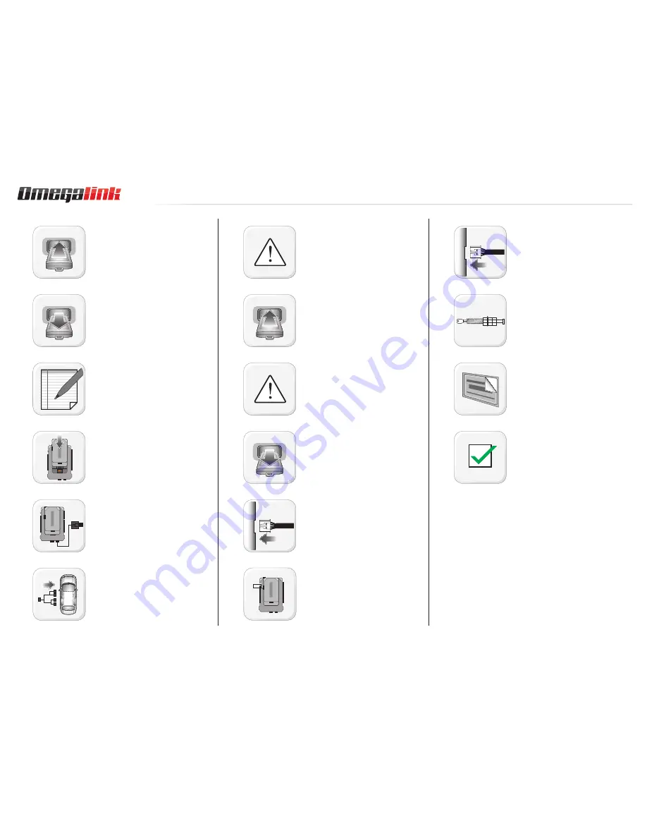
START vehicle. Verify all vehicle
functionalities. If the vehicle displays error
messages or any malfunction: stop the
installation and service the vehicle.
Turn ignition to OFF position. Remove keyfob
from keyport.
Verify all keyfob functionalities (Door Lock,
Door Unlock, Trunk Release and Comfort
Access System if equipped).
Insert the expansion pack into module.
Connect the module to the computer with the
WEBLINK cable. Flash the module with the
latest fi rmware then fl ash the expansion pack.
Connect and secure every connector to the
vehicle, as shown in STEP 1 of the WIRING
DIAGRAM.
WARNING: Any vehicle harness that is
disconnected during installation, must be
re-connected before performing any system
tests. Failure to comply will result in vehicle
displaying error messages. An OEM scantool
will be required to clear the error messages.
START vehicle. Verify all vehicle
functionalities.
WARNING: If the vehicle displays error
messages or any malfunction, stop the
installation, verify every connection and if the
problem persists, call technical support.
Turn ignition to OFF position. Remove keyfob
from keyport.
Connect and secure every connector to the
module, as shown in STEP 2 of the WIRING
DIAGRAM.
Connect and secure every connector of the
expansion cable to the module, as shown in
STEP 3 of the WIRING DIAGRAM.
If required, connect an accessory as shown
in the COMPATIBLE ACCESSORIES section of
the guide.
If the vehicle is not equipped with a factory
hood switch, install an aftermarket hood
switch as shown in STEP 4 of the WIRING
DIAGRAM.
Put sticker 1 on a clean and visible surface
in the engine bay and put sticker 2 under the
dashboard near the OBDII connector.
Module installation procedure completed.
www.omegaweblink.com
Automotive Data Solutions Inc. © 2015
OEM-IDS(RS)-BM1-[OL-RS-BM1]-EN
Page 5 oF 18
• 20150121
DOC.: #20456

![Preview for 1 page of Omega Link OEM-IDS(RS)-BM1-[OL-RS-BM1]-EN Install Manual](http://thumbs.mh-extra.com/thumbs/omega-link/oem-ids-rs-bm1-ol-rs-bm1-en/oem-ids-rs-bm1-ol-rs-bm1-en_install-manual_738444-01.webp)
![Preview for 2 page of Omega Link OEM-IDS(RS)-BM1-[OL-RS-BM1]-EN Install Manual](http://thumbs.mh-extra.com/thumbs/omega-link/oem-ids-rs-bm1-ol-rs-bm1-en/oem-ids-rs-bm1-ol-rs-bm1-en_install-manual_738444-02.webp)
![Preview for 3 page of Omega Link OEM-IDS(RS)-BM1-[OL-RS-BM1]-EN Install Manual](http://thumbs.mh-extra.com/thumbs/omega-link/oem-ids-rs-bm1-ol-rs-bm1-en/oem-ids-rs-bm1-ol-rs-bm1-en_install-manual_738444-03.webp)
![Preview for 4 page of Omega Link OEM-IDS(RS)-BM1-[OL-RS-BM1]-EN Install Manual](http://thumbs.mh-extra.com/thumbs/omega-link/oem-ids-rs-bm1-ol-rs-bm1-en/oem-ids-rs-bm1-ol-rs-bm1-en_install-manual_738444-04.webp)
![Preview for 5 page of Omega Link OEM-IDS(RS)-BM1-[OL-RS-BM1]-EN Install Manual](http://thumbs.mh-extra.com/thumbs/omega-link/oem-ids-rs-bm1-ol-rs-bm1-en/oem-ids-rs-bm1-ol-rs-bm1-en_install-manual_738444-05.webp)
![Preview for 6 page of Omega Link OEM-IDS(RS)-BM1-[OL-RS-BM1]-EN Install Manual](http://thumbs.mh-extra.com/thumbs/omega-link/oem-ids-rs-bm1-ol-rs-bm1-en/oem-ids-rs-bm1-ol-rs-bm1-en_install-manual_738444-06.webp)
![Preview for 7 page of Omega Link OEM-IDS(RS)-BM1-[OL-RS-BM1]-EN Install Manual](http://thumbs.mh-extra.com/thumbs/omega-link/oem-ids-rs-bm1-ol-rs-bm1-en/oem-ids-rs-bm1-ol-rs-bm1-en_install-manual_738444-07.webp)
![Preview for 8 page of Omega Link OEM-IDS(RS)-BM1-[OL-RS-BM1]-EN Install Manual](http://thumbs.mh-extra.com/thumbs/omega-link/oem-ids-rs-bm1-ol-rs-bm1-en/oem-ids-rs-bm1-ol-rs-bm1-en_install-manual_738444-08.webp)
![Preview for 9 page of Omega Link OEM-IDS(RS)-BM1-[OL-RS-BM1]-EN Install Manual](http://thumbs.mh-extra.com/thumbs/omega-link/oem-ids-rs-bm1-ol-rs-bm1-en/oem-ids-rs-bm1-ol-rs-bm1-en_install-manual_738444-09.webp)
![Preview for 10 page of Omega Link OEM-IDS(RS)-BM1-[OL-RS-BM1]-EN Install Manual](http://thumbs.mh-extra.com/thumbs/omega-link/oem-ids-rs-bm1-ol-rs-bm1-en/oem-ids-rs-bm1-ol-rs-bm1-en_install-manual_738444-10.webp)
![Preview for 11 page of Omega Link OEM-IDS(RS)-BM1-[OL-RS-BM1]-EN Install Manual](http://thumbs.mh-extra.com/thumbs/omega-link/oem-ids-rs-bm1-ol-rs-bm1-en/oem-ids-rs-bm1-ol-rs-bm1-en_install-manual_738444-11.webp)
![Preview for 12 page of Omega Link OEM-IDS(RS)-BM1-[OL-RS-BM1]-EN Install Manual](http://thumbs.mh-extra.com/thumbs/omega-link/oem-ids-rs-bm1-ol-rs-bm1-en/oem-ids-rs-bm1-ol-rs-bm1-en_install-manual_738444-12.webp)
![Preview for 13 page of Omega Link OEM-IDS(RS)-BM1-[OL-RS-BM1]-EN Install Manual](http://thumbs.mh-extra.com/thumbs/omega-link/oem-ids-rs-bm1-ol-rs-bm1-en/oem-ids-rs-bm1-ol-rs-bm1-en_install-manual_738444-13.webp)
![Preview for 14 page of Omega Link OEM-IDS(RS)-BM1-[OL-RS-BM1]-EN Install Manual](http://thumbs.mh-extra.com/thumbs/omega-link/oem-ids-rs-bm1-ol-rs-bm1-en/oem-ids-rs-bm1-ol-rs-bm1-en_install-manual_738444-14.webp)
![Preview for 15 page of Omega Link OEM-IDS(RS)-BM1-[OL-RS-BM1]-EN Install Manual](http://thumbs.mh-extra.com/thumbs/omega-link/oem-ids-rs-bm1-ol-rs-bm1-en/oem-ids-rs-bm1-ol-rs-bm1-en_install-manual_738444-15.webp)
![Preview for 16 page of Omega Link OEM-IDS(RS)-BM1-[OL-RS-BM1]-EN Install Manual](http://thumbs.mh-extra.com/thumbs/omega-link/oem-ids-rs-bm1-ol-rs-bm1-en/oem-ids-rs-bm1-ol-rs-bm1-en_install-manual_738444-16.webp)
![Preview for 17 page of Omega Link OEM-IDS(RS)-BM1-[OL-RS-BM1]-EN Install Manual](http://thumbs.mh-extra.com/thumbs/omega-link/oem-ids-rs-bm1-ol-rs-bm1-en/oem-ids-rs-bm1-ol-rs-bm1-en_install-manual_738444-17.webp)
![Preview for 18 page of Omega Link OEM-IDS(RS)-BM1-[OL-RS-BM1]-EN Install Manual](http://thumbs.mh-extra.com/thumbs/omega-link/oem-ids-rs-bm1-ol-rs-bm1-en/oem-ids-rs-bm1-ol-rs-bm1-en_install-manual_738444-18.webp)


