Table Of Contents
Installation Considerations ��������������������������������������������������������������������������������������� 2
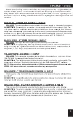
5 Pin Main Harness����������������������������������������������������������������������������������������������������� 3
Red Wire - Constant Power (+) Input ����������������������������������������������������������������������� 3
Black Wire - System Ground (-) Input ���������������������������������������������������������������������� 3
Yellow Wire - Ignition (+) Input���������������������������������������������������������������������������������� 3
Gray Wire - Trunk Release Disarm (+) Input ������������������������������������������������������������ 3
Orange Wire - Starter Interrupt (-) Output & Relay ��������������������������������������������������� 3
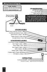
8 Pin Secondary Harness ������������������������������������������������������������������������������������������ 4
Pink Wire - 3rd Channel (-) Output ��������������������������������������������������������������������������� 4
White/Black Wire - Flashing Light (-) Output ������������������������������������������������������������ 4
White Wire - Flashing Light (+) Output ��������������������������������������������������������������������� 4
Brown Wire - Siren (+) Output ���������������������������������������������������������������������������������� 4
Violet Wire - Door Trigger (+) Input �������������������������������������������������������������������������� 4
Blue Wire - Hood Trigger (-) Input ���������������������������������������������������������������������������� 4
Green Wire - Door Trigger (-) Input �������������������������������������������������������������������������� 4
Brown/Black Wire - Horn Honk (-) Output ���������������������������������������������������������������� 4
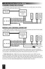
6 Pin Arm & Disarm Harness ������������������������������������������������������������������������������������� 5
White Wire - Arm Override Input ������������������������������������������������������������������������������ 5
Brown Wire - Disarm Override Input ������������������������������������������������������������������������ 5
Pink Wire - Arm Sensing Input ��������������������������������������������������������������������������������� 5
Gray Wire - Disarm Sensing Input ���������������������������������������������������������������������������� 5
Blue Wire - Lock (+) Pass-Through �������������������������������������������������������������������������� 5
Green Wire - Unlock (+) Pass-Through �������������������������������������������������������������������� 5
Wiring Overview Diagram ������������������������������������������������������������������������������������������ 7
6 Pin Arm & Disarm Harness Wiring ������������������������������������������������������������������������� 8
Standard Connection (Type #5) ������������������������������������������������������������������������������� 8
Parking Light Override Connection �������������������������������������������������������������������������� 8
3 Pin Door Lock/Unlock Port (RED) �������������������������������������������������������������������������� 9
2 Pin Backup Battery Port (WHITE) �������������������������������������������������������������������������� 9
Data Port (GREEN) ����������������������������������������������������������������������������������������������������� 9
Dual Zone Sensor Port (WHITE) �������������������������������������������������������������������������������� 9
The Status Light ��������������������������������������������������������������������������������������������������������� 9
Valet / Programming Switch �������������������������������������������������������������������������������������� 9
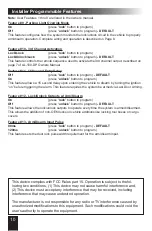
Installer Programmable Features���������������������������������������������������������������������������� 10
Programmable Features �������������������������������������������������������������������������������������������11
Programmable Feature Matrix ����������������������������������������������������������������������������������11
Installation Considerations
BEFORE STARTING THE INSTALLATION, READ THIS ENTIRE MANUAL
TO FAMILIARIZE YOURSELF WITH ANY INSTALL REQUIREMENTS
• Be sure to verify each circuit with a Digital Multimeter
• Identify which circuits are required for the vehicle in question
• Mount any system components and route wiring away from moving parts
or parts of the vehicle that generate excessive heat
• Tape off or remove any unused wiring to prevent possible short circuits
• Avoid any airbag circuits, usually indicated by a yellow
sleeve or jacket around the wiring


