3
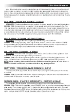
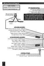
5 Pin Main Harness
Most of the main wiring harness connections are primary power circuits, so high reliability con-
nections must be made� It is recommended to solder and adequately insulate each connection�
Many of these connections are made at the vehicle’s ignition switch so be sure to properly route
the harness away from steering wheel tilt mechanisms or anything that could compromise the wire
insulation�
RED WIRE - CONSTANT POWER (+) INPUT
REQUIRED�
This wire provides constant positive 12v power supply for the system’s operation�
CONNECTION:
Connect this to a co12 volt supply with sufficient amperage (15A). The
+12v power supply to the ignition switch or direct connection to the car battery is ideal� Some ve-
hicles have low amperage ignition switches in which case you would need to find a power supply
at a fuse block or at the vehicle’s battery� Be sure this wire is fused within 6 inches of the connec-
tion to the vehicle� The 15AMP fuse protects the system module, NOT THE VEHICLE�
BLACK WIRE - SYSTEM GROUND (-) INPUT
REQUIRED�
This input provides negative ground for all system operations�
CONNECTION:
Using a properly sized ring terminal, connect this wire to the vehicle’s chassis�
Using an existing bolt is preferred, but make sure that the connection point is clean and free of
dirt, grease, or paint� Bright, shiny metal at the connection point is desired�
YELLOW WIRE - IGNITION (+) INPUT
REQUIRED�
This connection is required and is critical to the operation of the system� It is an
“IGNITION ON” input when the ignition key is turned on�
CONNECTION:
The vehicle’s primary ignition circuit is typically found at the ignition switch� The
proper circuit will show +12v when the ignition key is in the ON/RUN and START positions�
NOTE: When installing with an aftermarket or OEM remote start systems be sure the wire
shows +12V with remote start operation as well as key start operation�
GRAY WIRE - TRUNK RELEASE DISARM (+) INPUT
The Gray wire is the (+) Trunk Release Disarm Input; a 12v pulse on this wire will disarm the
AL-100-DP�
CONNECTION:
Connect this wire to the vehicle’s existing trunk release motor wire which shows
12V when the OEM remote is used to open the trunk�
ORANGE WIRE - STARTER INTERRUPT (-) OUTPUT & RELAY
This provides 500mA negative ground while the alarm is armed for the starter kill relay�
CONNECTION:
This wire is connected to the ORANGE input wire on the included starter interrupt
relay socket� Then, locate the vehicle’s (+) starter wire at the ignition switch and cut it� Connect
the starter interrupt relay’s RED wire to the ignition switch side of the cut starter wire� Connect the
starter interrupt relay’s WHITE wire to the starter side of the cut starter wire�


