background image

4

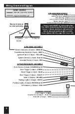
BROWN WIRE - SIREN (+) OUTPUT


This output provides a 1 amp positive output to operate an optional siren�

CONNECTION:

 Safely route this wire to the chosen mounting location of the siren and connect it 

to the siren’s red wire� Connect the siren’s black wire to chassis ground�

BLUE WIRE - HOOD TRIGGER (-) INPUT


This input is used to detect entry into the hood area of the vehicle� 

CONNECTION:

 Connect this wire to the vehicle’s existing hood switch or light� It will show ground 

when the hood is opened� You can also use the included pin switch and mount it to the radiator 

core support� 

GREEN WIRE - DOOR TRIGGER (-) INPUT


This input is used to detect entry into the vehicle via any door opening� 

CONNECTION:

 Connect this wire to the vehicle’s existing dome light circuit or door pin circuit� 

The circuit will show ground when any door is opened� If you are required to connect to each 

individual door pin, diode isolation is required� Use one 1-2 amp diode for each door, facing the 

diode’s cathode (stripe) towards the vehicle wiring�

VIOLET WIRE - DOOR TRIGGER (+) INPUT


This input is used to detect entry into the vehicle via any door opening� 

CONNECTION:

 Connect this wire to the vehicle’s existing dome light circuit or door pin circuit� 

The circuit will show +12 volts when any door is opened� If you are required to connect to each 

individual door pin, diode isolation is required� Use one 1-2 amp diode for each door, facing the 

diode’s cathode (stripe) towards the alarm module�

BROWN/BLACK WIRE - HORN HONK (-) OUTPUT


This output provides a 250mA negative output to honk the vehicle’s horn� If the vehicle has a 

positive parking horn circuit, use a relay to convert the output� 

CONNECTION:

 Connect this wire to the vehicle’s horn circuit� It will show ground when the horn 

button is pressed� 

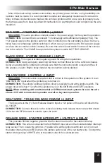
8 Pin Secondary Harness

WHITE/BLACK WIRE - FLASHING LIGHT (-) OUTPUT


This output provides a 250mA negative output to flash the vehicle’s parking lights (typically). If 

the vehicle has a positive parking light circuit, use the WHITE wire instead�

CONNECTION:

 Connect this wire to the vehicle’s negative parking light circuit� It will show ground 

when the parking lights are on� 

BE SURE NOT TO CONNECT TO THE DIMMER CIRCUIT 

WHICH WILL CHANGE RESISTANCE TO GROUND AS YOU TURN THE DIMMER KNOB�

PINK WIRE - 3RD CHANNEL (-) OUTPUT


This output provides a 250mA negative output for 800ms when the CH3 sequence is activated 

by the controller� This sequence is selectable with programmable feature #10

CONNECTION:

 Connect this wire to any desired add-on accessory that can utilize a negative 

activation input�

WHITE WIRE - FLASHING LIGHT (+) OUTPUT


This output provides a 10 amp positive output to flash the vehicle’s parking lights (typically). If 

the vehicle has a low current negative parking light circuit, use the WHITE/BLACK wire instead�

CONNECTION:

 Connect this wire to the vehicle’s positive parking light circuit� It will show +12 

volts when the parking lights are on� 

BE SURE NOT TO CONNECT TO THE DIMMER CIRCUIT 

WHICH WILL CHANGE VOLTAGE AS YOU TURN THE DIMMER KNOB�

Summary of Contents for AL-100DP

Page 1: ...AL 100 DP Full Feature Vehicle Security System for Factory Equipped Remote Keyless Entry Transmitters Installation Guide ...

Page 2: ...ock Pass Through 5 Wiring Overview Diagram 7 6 Pin Arm Disarm Harness Wiring 8 Standard Connection Type 5 8 Parking Light Override Connection 8 3 Pin Door Lock Unlock Port RED 9 2 Pin Backup Battery Port WHITE 9 Data Port GREEN 9 Dual Zone Sensor Port WHITE 9 The Status Light 9 Valet Programming Switch 9 Installer Programmable Features 10 Programmable Features 11 Programmable Feature Matrix 11 Ins...

Page 3: ...ake sure that the connection point is clean and free of dirt grease or paint Bright shiny metal at the connection point is desired YELLOW WIRE IGNITION INPUT REQUIRED This connection is required and is critical to the operation of the system It is an IGNITION ON input when the ignition key is turned on CONNECTION The vehicle s primary ignition circuit is typically found at the ignition switch The ...

Page 4: ...ng the diode s cathode stripe towards the alarm module BROWN BLACK WIRE HORN HONK OUTPUT This output provides a 250mA negative output to honk the vehicle s horn If the vehicle has a positive parking horn circuit use a relay to convert the output CONNECTION Connect this wire to the vehicle s horn circuit It will show ground when the horn button is pressed 8 Pin Secondary Harness WHITE BLACK WIRE FL...

Page 5: ...Parking Light Override Operation feature 9 this wire must see a change in polarity within 1 second of the White wire for the AL 100 DP to arm CONNECTION In both operation modes this wire is connected to the all Door Lock Motor wire that shows a polarity change when the OEM remote is used to lock the vehicle GRAY WIRE DISARM SENSING INPUT This wire is the disarm input wire In Standard Operation any...

Page 6: ... PIN SECONDARY HARNESS Horn Honk Output BROWN BLACK Door Trigger Input GREEN Hood Trigger Input BLUE Door Trigger Input VIOLET Siren Output BROWN Parking Light Output WHITE Parking Light Output WHITE BLACK 3rd Channel Output PINK 10 AMP Starter Interrupt socket and relay To Starter To Ignition Switch White Red cut starter wire 3 PIN DOOR LOCK PORT Lock Output GREEN Constant 12v Output Center Pin U...

Page 7: ... WHITE BLACK LIGHT PINK 3rd CH AL 100 DP DOOR LOCK SENSOR PORT Slide Bracket For Backup Battery Other Accessories Green Interface Module Data Port Backup Battery Port 4 PIN SENSOR PORT Pre warn Input GREEN Trigger Input BLUE Ground Output BLACK Constant 12v Output RED Status Light Valet Switch Adhesive Pad Status Light Valet Holder 1 Screws ...

Page 8: ...n to the Hazard Parking light circuit If the Hazard Parking lights do not flash with the Lock operation connect the White wire with the Pink to the All Door Motor Lock circuit Parking Light Override Connection can be used in vehicles that flash the Hazard Parking lights when the OEM remote Lock or Unlock buttons are pressed Feature 9 Auto Learn Within 60 seconds of applying power to the AL 100 DP ...

Page 9: ... The included valet switch can be dash mounted directly or using the combo valet switch status light holder Dual Zone Sensor Port WHITE This system is equipped with a white dual zone sensor port Any Omega single or dual zone sensor will plug directly into this port A dual zone shock sensor is included with this system Data Port GREEN This port provides a direct digital interface for any Omega Inte...

Page 10: ... unlock button to program DEFAULT This feature allows the lock unlock outputs to operate every time the system is armed disarmed This allows the addition of non OEM locks on vehicle additions like locking tool boxes or cargo covers Feature 13 Arm Disarm Input Pulse 80ms press lock button to program DEFAULT 120ms press unlock button to program This feature sets the door lock pulse width requirement...

Page 11: ...eps 3 4 at this time Step 6 To exit programming turn the ignition key ON then OFF Or you can wait 10 seconds for programming mode to expire Feature Programming Ignition on off press valet 5 times Feature Lock Button Unlock Button User Features 1 Confirmation Chirps On Off 2 Last Door Arming On Off 3 Automatic Rearming On Off 4 Lock w Last Door Arming On Off 5 Lock w Automatic Rearm On Off 6 Igniti...

Page 12: ...AL 100 DP_MI 6 2 2016 Visit us online at www CarAlarm com Tech Support 800 554 4053 Find us on Facebook http facebook com OmegaRD Copyright 2016 Omega Research Development Technologies Inc ...

Reviews: