PLATINUM
TM
Series Controllers User
’s
Guide
M5451
Omega Engineering | www.omega.com
10
Wiring Instructions
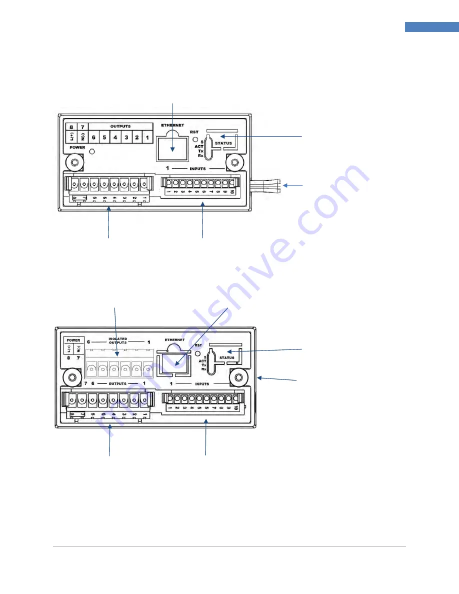
Ethernet Communications Status
LEDs if EIP Option Installed
USB Connector (on side,
shown with cable stub)
8-Pin Power / Base Outputs Connector
10-Pin Input Connector
Ethernet Connector if EIP Option Installed
3.
Wiring Instructions
3.1
Back Panel Connections
Figure 1
–
CN8Pt, CN8DPt and CN8EPt
Models: Back Panel Connections
(No Isolated Output Expansion Board Installed)
Figure 2
–
CN8Pt, CN8DPt and CN8EPt Models: Back Panel Connections
(With Isolated Output Expansion Board)
10-Pin Input Connector
8-Pin Power / Base Outputs Connector
USB Connector (on
side, not visible here)
Ethernet Communications Status
LEDs if EIP Option Installed
Ethernet Connector if EIP Option Installed
Optional Isolated Output Expansion
Connector


