PLATINUM
TM
Series Controllers User
’s
Guide
M5451
Omega Engineering | www.omega.com
13
Wiring Instructions
External
Excitation
Internal
1
2
3
4
5
6
7
8
9
10
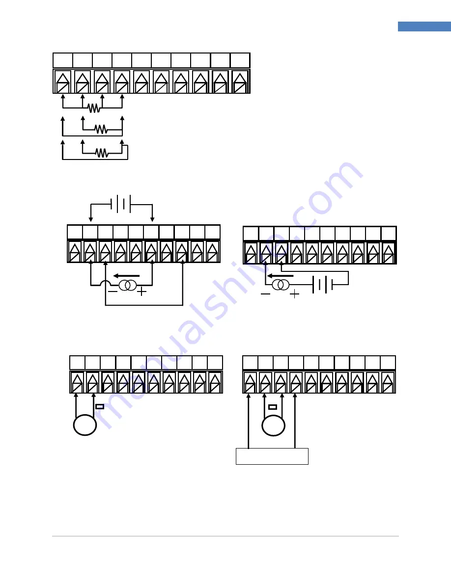
Figure 5
–
RTD Wiring Diagram
Figure 6
–
Process Current Wiring Hookup with Internal and External Excitation
Figure 7
–
Process Voltage Wiring Hookup with optional Ratiometric Voltage connection.
1
2
3
4
5
6
7
8
9
10
RTD (100 Ω) 4-WIRE
RTD (100 Ω) 3-WIRE
RTD (100 Ω) 2-WIRE (requires
pin 1 to be jumped to pin 4)
1
2
3
4
5
6
7
8
9
10
0–24 mA
Internal
Excitation
1
2
3
4
5
6
7
8
9
10
1
2
3
4
5
6
7
8
9
10
V
V
+/- 10, +/- 1 and +/- 0.1
Single End Voltage
+/- 0.1and +/- .05 Differential /
Ratiometric Voltage
Reference Voltage


