PLATINUM
TM
Series Controllers User
’s
Guide
M5451
Omega Engineering | www.omega.com
18
Complete Menu Structure
5.
Complete Menu Structure
5.1
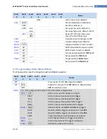
Initialization Mode Menu (INIt)
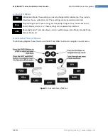
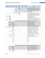
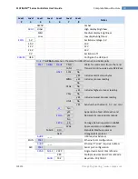
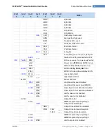
The following table maps the Initialization Mode (
) navigation:
Level
2
Level
3
Level
4
Level
5
Level
6
Level
7
Level
8
Notes
k
Type K thermocouple
J
Type J thermocouple
t
Type T thermocouple
E
Type E thermocouple
N
Type N thermocouple
R
Type R thermocouple
S
Type S thermocouple
b
Type B thermocouple
C
Type C thermocouple
3 wI
3-wire RTD
4 wI
4-wire RTD
2 wI
2-wire RTD
385.1
385 calibration curve, 100
Ω
385.5
385 calibration curve, 500 Ω
385.t
385 calibration curve, 1000 Ω
392
392 calibration curve, 100 Ω
391.6
391.6 calibration curve, 100 Ω
2.25k
2250 Ω thermistor
5k
5000 Ω thermistor
10k
10,000 Ω thermistor
4
–
20
Process input range: 4 to 20 mA
Note:
This Manual and Live Scaling submenu is the same for all
PRoC
ranges.
MANL
Rd.1
____
Low display reading
IN.1
____
Manual input for Rd.1
Rd.2
____
High display reading
IN.2
____
Manual input for Rd.2
LIVE
Rd.1
____
Low display reading
IN.1
____
Live Rd.1 input, ENTER for current
Rd.2
____
High display reading
IN.2
____
Live Rd.2 input, ENTER for current
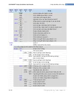
0
–
24
Process input range: 0 to 24 mA
+-10
Process input range: -10 to +10 V
Note:
+- 1.0 and +-0.1 support SNGL, dIFF and RtIO
tYPE
+-1
tYPE
SNGL
Process input range: -1 to +1 V


