PLATINUM
TM
Series Controllers User
’s
Guide
M5451
Omega Engineering | www.omega.com
50
Reference Section: Programming Mode (PRoG)
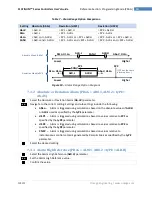
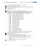
Table 7
–
Alarm Range Option Comparison
Setting
Absolute (AbSo)
Deviation (d.SP1)
Deviation (d.SP2)
AboV
> ALR.H
> SP1 + ALR.H
> SP2 + ALR.H
bELo
< ALR.L
< SP1 - ALR.L
< SP2 - ALR.L
HI.Lo.
< ALR.L or > ALR.H
< SP1 - ALR.L or > SP1 + ALR.H
< SP2 - ALR.L or > SP2 + ALR.H
bANd
> ALR.L and < ALR.H
> SP1 - ALR.L and < SP1 + ALR.H
> SP2 - ALR.L and < SP2 + ALR.H
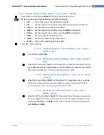
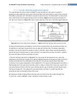
Absolute Mode (AbSo)
Deviation Mode (dEVI)
Figure 10
–
Alarm Range Option Diagram
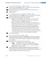
7.3.2
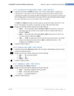
Absolute or Deviation Alarm (PRoG > ALM.1, ALM.2 > tyPE >
Ab.dV)
Select the Absolute or Deviation Alarm (
Ab.dV
) parameter.
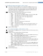
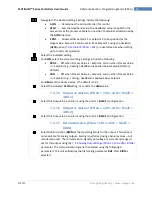
Navigate to the correct setting. Settings and sub settings include the following:
AbSo
–
Alarm is triggered using calculations based on the absolute values of
ALR.H
or
ALR.L
used as specified by the
tyPE
parameter
d.SP1
–
Alarm is triggered using calculations based on values relative to
SP1
as
specified by the
tyPE
parameter
d.SP2
–
Alarm is triggered using calculations based on values relative to
SP2
as
specified by the
tyPE
parameter.
CN.SP
–
Alarm is triggered using calculations based on values relative to
instantaneous control setpoint generated by Ramp & Soak as specified by the
tyPE
parameter.
Select the desired setting.
7.3.3
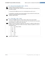
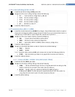
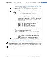
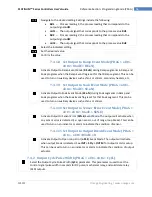
Alarm High Reference (PRoG > ALM.1, ALM.2 > tyPE > ALR.H)
Select the Alarm High Reference (
ALR.H
) parameter.
Set the Alarm High Reference value.
Confirm the value.
bANd
AboV
,
HI.Lo.
bELo
,
HI.Lo.
Higher
Lower
ALR.L
ALR.H
(SP2 has the same
alarm options.)
SP1
SP2
bANd
Higher
Lower
ALR.L
bELo, HI.Lo.
ALR.H
AboV, HI.Lo.


