PLATINUM
TM
Series Controllers User
’s
Guide
M5451
Omega Engineering | www.omega.com
51
Reference Section: Programming Mode (PRoG)
7.3.4
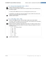
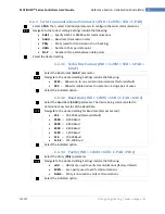
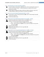
Alarm Low Reference (PRoG > ALM.1, ALM.2 > tyPE > ALR.L)
Select the Alarm Low Reference (
ALR.L
) parameter.
Set the Alarm Low Reference value.
Confirm the value.
7.3.5
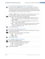
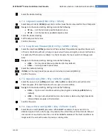
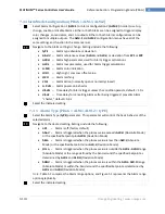
Alarm Color (PRoG > ALM.1, ALM.2 > A.CLR)
Select the Alarm Color (
A.CLR
) parameter.
Navigate to the desired option. Options include the following:
REd
–
Alarm conditions are displayed in red (factory default)
AMbR
–
Alarm conditions are displayed in amber
GRN
–
Alarms conditions are displayed in green
dEFt
–
Alarms do not affect the default display color
Select the desired option.
7.3.6
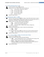
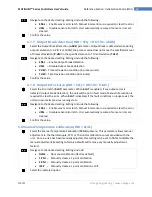
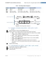
Alarm High High / Low Low Offset Value (PRoG > ALM.1, ALM.2 >
HI.HI)
Select the Alarm Offset Value (
HI.HI
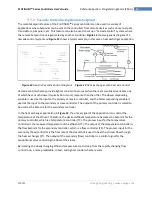
) parameter. This parameter allows an offset to be added
to the Alarm trigger point(s) which will flash the display when exceeded. Depending on the
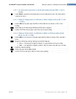
Alarm type the offset can apply above the trigger point, below it, or both. This is illustrated in
Figure 5.2.
HI.HI
works with both absolute and deviation Alarms.
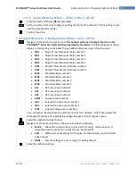
Navigate to the correct option. Options include the following:
oFF
–
High High / Low Low function disabled (factory default)
oN
–
Display will flash in the color determined by the
A.CLR
parameter when the
Process Value is greater than the HI.HI offset value away from the Alarm condition
settings (in either direction)
Select the indicated option.
For
oN
, set the offset value.
Confirm the value.
Figure 11
–
Alarm HI.HI parameter.
Higher
Lower
bANd
AboV
,
HI.Lo.
bELo
,
HI.Lo.
ALR.L
ALR.H
Lo.Lo
HI.HI

