5.
OPERATING INSTRUCTIONS
5.1
Preparation and Warm Up
It is assumed that the Mass Flow Controller has been correctly installed and thor-
oughly leak tested as described in section (2). Shut the flow source OFF. Apply
power to the unit via the 15-pin “D” connector. Before connecting the power sup-
ply check the controller power supply requirements label located on the controller
back cover. If the power supply requirements label states that power supply
requirement is 12 Vdc, do not connect the power supply with voltage above 15
Vdc. Exceeding the specified maximum power supply voltage limit will result in
device permanent damage. Allow the Mass Flow Controller to warm-up for at
least 15 minutes.
During initial powering of the FMA 5400A/5500A transducer, the flow output sig-
nal will be indicating a higher than usual output. This is indication that the FMA
5400A/5500A transducer has not yet attained it's minimum operating tempera-
ture. This condition will automatically cancel within a few minutes and the trans-
ducer should eventually zero.
If after the 15 minutes warm-up period, the display still indicates a reading of less
than ± 3.0 % of F.S., readjust the ZERO potentiometer [R34] through the access
window. Before zero adjustment to temporarily disconnect the gas source, to
ensure that no seepage or leak occurs in to the meter.
11
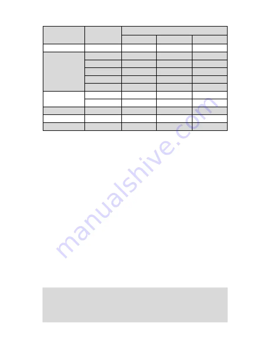
TABLE I
PRESSURE DROPS
MAXIMUM FLOW
RATE SERIES
FLOW RATE
[liters/min]
MAXIMUM PRESSURE DROP
[mm H
2
O]
[psid]
[mbar]
10 L/min
up to 10
720
1.06
75
50 L/min
15
2630
3.87
266
20
1360
2.00
138
30
2380
3.50
241
40
3740
5.50
379
50
5440
8.00
551
100 L/min
60
7480
11.00
758
100
12850
18.89
1302
200 L/min
200
7031
10.00
690
500 L/min
500
8437
12.00
827
1000 L/min
1000
10547
15.00
1034
CAUTION: Adjusting Zero Reading more than ± 3.0% F.S. from the
factory settings may affect device calibration accuracy. If such adjustment
is required it is recommended to perform controller recalibration to pre
serve device accuracy.


