background image

FMG490 INSTRUCTIONS

Page 15 

CONNECTIONS

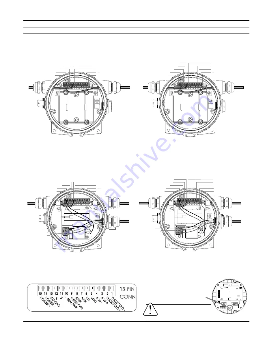
Wiring Diagrams (Remote Display)

Remove the 3 screws holding the display assembly and remove it from the meter.  Remove the 15 pin screw connector 

from its bag. Install the wires through the cable glands into the 15 pin screw connector in their respective locations. Plug 

the 15 pin screw connector into its socket.  

(C1 = power/output cable 1, C2 = power/output cable 2, R = remote cable)

DC Power with Pulse and 4-20mA (D5

I

/D6

I

)

DC Power with Pulse (D5N/D6N)

Plug the backup battery 

cable into the back of the 

display assembly.

Black (R) -Remote Pwr: pn10

Red (R) +Remote Pwr: pn9

Green (C1) Pulse+: pn2

White (C1) Pulse-: pn1

Orange (R) Remote B: pn11

Blue (R) Remote A: pn12

Black (C1) DC-: pn14

Red (C1) DC+: pn15

C1

R

C1

R

Red (R) +Remote Pwr: pn9

Blue (C1) 4-20mA-: pn4

Orange (C1) 4-20mA+: pn3

Green (C1) Pulse+: pn2

White (C1) Pulse-: pn1

Black (R) -Remote Pwr: pn10

Orange (R) Remote B: pn11

Blue (R) Remote A: pn12

Black (C1) DC-: pn14

Red (C1) DC+: pn15

WARNING: BACKUP BATTERIES 

ARE NOT INTENDED AS A PRIMARY 

POWER SOURCE OF A MAINS 

(DC or AC) CONFIGURED METER.

Remove the 3 screws holding the display assembly and remove it from the meter.  Remove the 15 pin screw connector 

from its bag. Install the wires through the cable glands into the 15 pin screw connector in their respective locations. Plug 

the 15 pin screw connector into its socket. 

(C1 = power/output cable, R = remote cable, AC = AC power cable)

AC Power with Pulse and 4-20mA (A5

I

/A6

I

)

AC Power with Pulse (A5N/A6N)

Black (Line)

White (Neutral)

Green (Ground)

Black (R) -Remote Pwr: pn10

Red (R) +Remote Pwr: pn9

Green (C1) Pulse+: pn2

White (C1) Pulse-: pn1

Orange (R) Remote B: pn11

Blue (R) Remote A: pn12

Black (Internal): pn14

Red (Internal): pn15

C1

R

AC

Black (Line)

White (Neutral)

Green (Ground)

Red (R) +Remote Pwr: pn9

Blue (C1) 4-20mA: pn4

Orange (C1) 4-20mA+: pn3

Green (C1) Pulse+: pn2

White (C1) Pulse-: pn1

Black (R) -Remote Pwr: pn10

Orange (R) Remote B: pn11

Blue (R) Remote A: pn12

Black (Internal): pn14

Red (Internal): pn15

C1

R

AC

Summary of Contents for FMG490 Series

Page 1: ...e mail info omega com For latest product manuals omega com en us pdf manuals XXXXXX Xxxxx Xxxxxxxx Shop online at omega com User sGuide TM FMG490 SERIES Municipal Industrial Magmeter...

Page 2: ...ns without notice omega com info omega com Servicing North America U S A Omega Engineering Inc 800 Connecticut Ave Suite 5N01 Norwalk CT 06854 Headquarters Toll Free 1 800 826 6342 USA Canada only Cus...

Page 3: ...onfiguration Sourcing Mode Output Application Page 16 Sinking Mode Output Application Page 16 Analog 4 20mA Current Loop Output Application Page 16 Cable Shield Page 17 Pulse Output Page 17 Analog 4 2...

Page 4: ...t flow batch forward flow and batch reverse flow Batch totals can be reset Built in data logging is available as an option for secure flow logging Scaled pulse output is standard and one additional ou...

Page 5: ...gal Cubic Meters Cubic Meters x 1000 Cubic Feet Cubic Feet x 1000 Second Foot Day Million Cubic Feet Acre Feet Acre Inches Imperial Gallons Imperial Gallons x 1000 Million Imperial Gallons Fluid Ounce...

Page 6: ...ter Size L H T ID Shipping Weight inch mm inch mm inch mm inch mm lbs Kg 3 12 25 311 7 08 179 8 68 17 25 2 6 66 04 40 18 4 10 12 257 8 3 211 62 15 7 3 12 79 43 19 5 6 12 09 307 9 1 231 69 17 5 5 05 12...

Page 7: ...0 6 8 10 FMG490 Accuracy Pipe Size Inches in diameter 3 4 6 8 10 12 Max Flow Rate Gallons Minute 723 1285 2891 5140 8031 11565 Cut off min Flow Rate Gallons Minute 3 62 6 43 14 46 25 70 40 15 57 82 M...

Page 8: ...ing Flow Propeller Meter Partially Open Butterfly Valve 1X 1X 1X 1X Swirling Flow NOTE These configurations are to be used as general guidelines and do not cover every possible installation A combinat...

Page 9: ...ent on the electrodes can affect accuracy Recommended Improved accuracy results from unimpeded electrodes Electrode moved from top by rotating meter Intermittent air bubbles miss electrode Electrodes...

Page 10: ...er ANSI 150 lb flanges See table on page 11 for flange bolt tightening torque specifications Calibration The FMG490 meters are factory calibrated and will not require any form of field calibration Che...

Page 11: ...tem must be grounded to meet national and local electrical safety codes Failure to do so can result in electrocution Equalization Lug Meter Flange Pipe Flange Gasket Pipe Flange Flange Plate Lockwashe...

Page 12: ...e 1 Cable Gland Opening and Sealing The display is available in either DC or AC versions DC version AC Version If the meter is configured with AC power one of the additional Power Output cable ports m...

Page 13: ...latory agency approval If installed outdoors or less than 33ft 10m from a utility power service entrance AC power should be supplied via a properly grounded surge suppression device 10 Remove the plug...

Page 14: ...sensor cable inside the internal strain relief clip and tighten the cable gland sealing nut securely torque strain relief sealing gland dome nut to 22 in lbs A lose nut could cause moisture ingress an...

Page 15: ...ange R Remote B pn11 Blue R Remote A pn12 Black C1 DC pn14 Red C1 DC pn15 WARNING BACKUP BATTERIES ARE NOT INTENDED AS A PRIMARY POWER SOURCE OF A MAINS DC or AC CONFIGURED METER Remove the 3 screws h...

Page 16: ...D5L D6L RED C1 BLACK C1 BLUE R ORNG R BLACK R RED R BLUE C1 ORNG C1 GREEN C1 WHITE C1 A5N A6N RED INT BLACK INT BLUE R ORNG R BLACK R RED R GREEN C1 WHITE C1 A5L A6L RED INT BLACK INT BLUE R ORNG R BL...

Page 17: ...pplication Sinking Mode Recommended for Rin 30k Analog 4 20mA Current Loop Output Application Minimum resistor value is 100 x Vs ohms Higher resistances maybe used depending on frequency and cable len...

Page 18: ...units totaled per pulse all sizes of meters can be configured with the same SETP values For example if your rate is chosen as gallons per minute GPM the table below applies If your rate is different...

Page 19: ...perform the hold and tap sequence When finished making changes When you are finished making changes move to the EXIT tab using the right button To return to the HOME screen perform the hold and tap s...

Page 20: ...g average SET 4 View or change flow rate corresponding to 4mA SET 20 View or change flow rate corresponding to 20mA EXIT Return to HOME SCREEN or enter SUBMENU T UNIT R UNIT SET P DAMP SET 4 SET 20 SE...

Page 21: ...the number of samples for rolling average of pulse output TEST TEST allows the user to initiate a fully functional artificial flow rate for the purpose of testing other connected equipment When TEST i...

Page 22: ...correct but pulse frequency output is low erratic or absent Wiring incorrect Compare wiring with appropriate wiring recommendations External device input impedance too low Use sourcing rather than sin...

Page 23: ...nation by OMEGA if the unit is found to be defective it will be repaired or replaced at no charge OMEGA s WARRANTY does not apply to defects resulting from any action of the purchaser including but no...

Page 24: ...as Mass Flowmeters Flow Computers Air Velocity Indicators Turbine Paddlewheel Systems Totalizers Batch Controllers pH CONDUCTIVITY pH Electrodes Testers Accessories Benchtop Laboratory Meters Controll...

Reviews: