


HFS Heat Flux Sensor Instruction Manual
4
Measuring Thermocouple Voltage
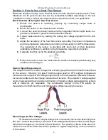
A thermocouple is integrated in every HFS heat flux sensor to provide a
measurement of the sensor’s surface temperature. Measuring the voltage output from the
thermocouple will provide an indication of the temperature difference between the
temperature measurement location at the top sensor surface and the voltage
measurement location. An additional temperature measurement at the voltage
measurement location is required to determine absolute temperature of the sensor. This
reference temperature is known as cold junction compensation and is commonly built into
data acquisition systems.
Connect the darker red constantan wire to a negative (-) terminal of the voltage
measurement device. The positive (+) voltage measurement device lead should be
connected to the blue copper lead wire.
Checking the Functionality of HFS Sensor & Troubleshooting
There are a couple different simple tests can be performed to ensure that the HFS is
operating correctly. It is good practice to perform these before & after mounting the sensor
so that inaccurate measurements are not accidently taken using a faulty sensor that may
have been damaged while it was being handled.
1.
Check Electrical Resistance of the Heat Flux Sensor:
Connect an ohmmeter to the bright red wire and the white wire leads to check the
heat flux sensor’s electrical resistance. It should <1000 Ω for HFS-5 sensors or <5
kΩ for HFS-6 & UHFS-09 sensors. If the resistance is much larger than this then
there may be an issue with the sensor. Resistance may be slightly larger for
sensors that have lead wire lengths longer than the standard 10 ft / 3 m. Infinite
electrical resistance (discontinuity) is an indication that the heat flux sensor is
broken.
2.
Check the Electrical Resistance of the Thermocouple:
Connect an electrical resistance ohmmeter to the darker red constantan wire and
the blue copper wire. The electrical resistance should be approximately 50 Ω for
our standard 10 foot / 3 meter lead length. Resistance will be higher for longer lead
lengths. Typical resistance of the wire is 5 Ω per foot or 16 Ω per meter. Infinite
electrical resistance (discontinuity) is an indication that the thermocouple is
broken.
3.
Check Output Voltage with Zero Heat Flux Through Sensor:
If possible, while a voltage measurement device is connected across the heat flux
wire leads, measure the output heat flux voltage while the sensor is experiencing
zero absorbed heat flux through the sensor. An easy scenario is to let the sensor
remain unmounted in ambient conditions such as sitting loose on a tabletop. The
analog DC voltage reading for the heat flux output voltage should be approximately
0.0 μV (+/- 5 μV can be contributed to electrical noise).


