
iDRN-ACV
AC VOLTAGE INPUT
General Description:
The iDRN Series of DIN rail-mountable signal conditioners
are available for Thermocouple, RTD, Strain, Process, AC
Voltage, AC Current and Pulse/Totalizer input types.
The factory calibrated signal conditioners are ideal for all
process and power monitoring applications, they feature
3-way isolation, high accuracy input, programmable outputs,
and are excellent front end interfaces for programmable logic
controllers or data acquisition systems. For maximum user
configurability the signal conditioners allow complete input-
output scaling via a RS-232 connection to any PC or PLC.
Software Description
:
The signal conditioner configuration program is a MS
DOS/Windows program (this manual is for the Windows
version). It is designed especially for the iDRN Series Signal
Conditioner. This program will run on any PC with Windows
application and will start automatically.
Free Serial Communication software and ActiveX Controls
are on the CD-ROM enclosed with this shipment.
To download the latest software release
(or request a free CD-ROM) please go to:
www.omega.com/software
What You need
:
•Your choice of the signal conditioner
•IBM PC or compatible
•Windows software 3.1 or higher, or Windows 95/98
•RJ12 connector with telephone cable
•Adapter (DB9 or DB25 to RJ12)
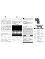
Setting up your System
COMPUTER
CONNECTION
(DB9 or DB25)
RJ12 CONNECTOR
with CABLE
ADAPTOR (DB9/25 to RJ12)
#DB9-RJ12, #DB25-RJ12
COMPUTER
POWER
CONNECTION
RS-232 to
RS-485
CONVERTER
HALF-DUPLEX
#CAT-285
SIGNAL
CONDITIONER MODULE
Operation:
Note:
When connecting a voltage signal, extra care should be
taken to prevent electrical shock. Always turn the signal
power off before making connections to the signal conditioner.
ALWAYS ENSURE THAT THE MAXIMUM VOLTAGE
INPUT
SIGNAL
DOES
NOT
EXCEED
400 VOLTS AC.
PLEASE
OBSERVE
THE
INPUT
SIGNAL
CONNECTION SPECIFIED IN THE SECTION
BELOW. THIS DEVICE MUST ONLY BE INSTALLED BY
A PROFESSIONAL ELECTRICIAN.
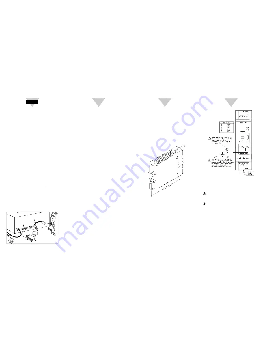
Power Input and Analog Output Setup:
To connect the signal input proceed as follows:
1.
Connect a DC power supply with an output voltage
between 10 to 32 Volt DC to the signal conditioner (J1).
Note:
If power supply used has current limiting, it may not
be able to power the signal conditioners if the available output
voltage is around 10 Volt, since the peak current may reach
1 to 5 amp for a few milliseconds.
2.
Determine the maximum voltage to be measured.
ANALOG OUTPUT LINEARITY:
0.1% of FS
ANALOG OUTPUT STEP RESPONSE TIME:
2 seconds to 99% of final value
INPUT POWER:
10 to 32 Volt DC
POWER CONSUMPTION
:
2.4 watts (100 mA at 24 Vdc)
OPERATING AMBIENT:
-5 to +55 °C
STORAGE TEMPERATURE:
-40 to +85 °C
RELATIVE HUMIDITY:
90% at 40 °C non-condensing
DIMENSIONS:
Introduction:
The AC voltage input signal conditioners are high
performance instruments that measure AC voltages in 4
ranges which are as follows: 400 mV, 4 Volt, 40 Volt and 400
Volt. Key features of the signal conditioners are built in active
attenuator, scalable analog output and a simple RS232
interface for scaling analog output and range selection. The
RS232 interface may also be used for digital transmission of
input signal to a computer or a PLC. Additional features
include three way isolation between DC power, signal input
and analog output/RS232.
INPUT RANGES:
400 mV, 4V, 40 Volt, 400 Volt
FREQUENCY RANGE:
30 Hz to 1 KHz
INPUT IMPEDANCE:
2.1 Meg for all ranges.
ISOLATION:
Dielectric strength per 1 minute test based on EN 61010 for
50 Vdc or Vrms working voltage.
Three way Isolation:
• Power to Signal Input: 1800V Peak
• Power to Analog Output/Communication: 1800V Peak
• Signal Input to Analog Output/Communication: 1400V
COMMON MODE REJECTION:
100 dB
INPUT OVER-VOLTAGE PROTECTION:
10% Above full scale continuously.
100% Above full scale for 10 seconds.
ANALOG TO DIGITAL TECHNIQUE:
Dual slope
READ RATE:
3 readings/second
ACCURACY AT 25 °C:
400 mV, 4V, 40V and 400V ranges
49 Hz to 500 Hz ±0.2% of FS
30 Hz to 1KHz ±0.2% of FS ±10 counts
TEMPERATURE STABILITY:
400 mV and 40 Volt range 150 ppm/°C typical
4V and 400 Volt range 100 ppm/°C typical
STEP RESPONSE FOR RS232 OUTPUT
:
2 seconds to 99% of the final value
(Filter time constant = 64)
RESPONSE TIME:
To verify the response time, check the carriage return <CR>,
it will be sent at the end of the response. You can send
another command after you receive the <CR>.
i.e.
send: *X01
response: X01<DATA><CR>
WARM UP TO RATED ACCURACY:
30 minutes
ANALOG OUTPUT SIGNAL TYPE:
Voltage: 0-10 Volt, maximum current 10mA
Current: 0-20 mA or 4-20 mA, maximum compliance
voltage 10 Volts (maximum loop resistance 500Ω)
START HERE
2
3
4
J 4
J 1
J 2
J 3
SIG HI
+
N/C
N/C
SIG LO


