OM-USB-2404-UI User's Guide
Functional Details
14
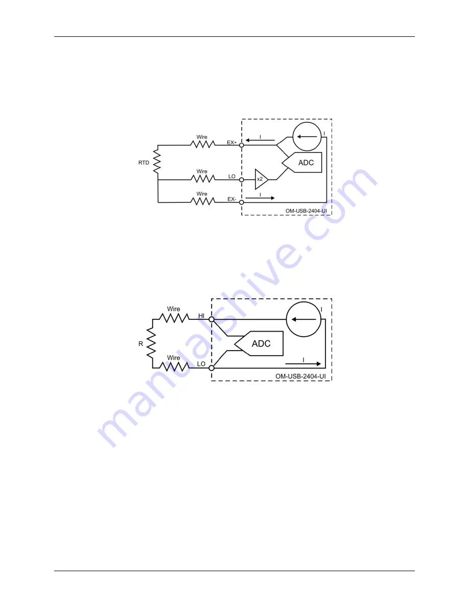
3-wire RTD mode
3-wire RTD mode sources a current which varies based on the resistance of the load between the EX+ and
EX– terminals. This mode compensates for lead wire resistance in hardware if all lead wires have the same
resistance. A gain of 2x is applied to the voltage across the negative lead wire. The ADC uses this voltage as the
negative reference to cancel the resistance error across the positive lead wire. 3-wire RTD mode connections are
shown in Figure 10.
Figure 10. 3-wire RTD mode connections
2-wire resistance and quarter-bridge modes
In 2-wire resistance and quarter-bridge modes, connect the two ends of the resistor or gauge to the OM-USB-
2404-UI across the HI and LO terminals. These modes source a current which varies based on the resistance of
the load between the HI and LO terminals. The resulting resistance is calculated from the voltage measurement.
2-wire and quarter-bridge modes do not compensate for lead wire resistance. 2-wire resistance and
quarter-bridge mode connections are shown in Figure 11.
Figure 11. 2-wire resistance and quarter-bridge mode connections
Half-bridge and full-bridge modes
Half-bridge and full-bridge modes use the internal voltage excitation to set the input range of the ADC, and
return voltage readings that are proportional to the excitation level. The internal excitation voltage is nominally
2.5 V, but it can vary based on the resistance of the sensor. Refer to the
Specifications
chapter for more
information about excitation levels.
In half-bridge mode, the HI input is referenced to EX–. In full-bridge mode, the ADC reads the HI and LO
inputs differentially.


