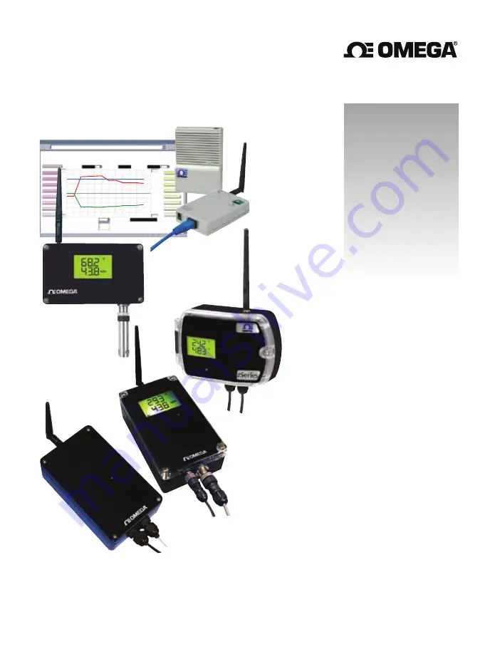
background image

zSeries Wireless 

Sensor System

zED, zED-P, zED-LCD,

zED-LCD-AA, zED-DC-H2,

zED-CCELL, zED-H, zCDR

User’s Guide

®

®

Shop on line at

omega.com  

e-mail: info@omega.com

For Latest Product Manuals

omegamanual.info

zSeries Wireless 

Sensor System

zED, zED-P, zED-LCD, 

zED-LCD-AA, zED-DC-H2,

zED-CCELL, zED-H, zCDR

zSeries

Group A

Main Menu

CHART

(5 Seconds/Div)

1 Minute
1 Minute

1 Day

1 Week

1 Month

1 Year

0

5

C/Div

50

1200

300

100%

0%

10

%/Div

90

hPa/Div

LAB 50  RH

LAB 50  Pres

C

hPa

Tue Jun 5 18:11:55 PDT 2009

Tue Jun 5 18:05:27 PDT 2009

http://192.168.1.200

LAB 50 Temp

35

1009

/25

P0 Primary

P1 LAB 50

P2 LAB 100

P3 CLN RM1

P4 CLN RM2

P5 Primary

P6 OVEN5

P7 Primary

S0 Secondary

S1 LAB 50

S2 LAB 100

S3 CLN RM1

S4 CLN RM2

S5 Secondary

S6 OVEN5

S7 Secondary

Save Current Graph

  e-mail: info@omega.com

For latest product manuals: 

www.omegamanual.info

Shop online at 

omega.com

SM

User’s Guide

• RoHS 2 Compliant

Summary of Contents for z Series

Page 1: ...inute 1 Minute 1 Day 1 Week 1 Month 1 Year 0 5 C Div 50 1200 300 100 0 10 Div 90 hPa Div LAB 50 RH LAB 50 Pres C hPa Tue Jun 5 18 11 55 PDT 2009 Tue Jun 5 18 05 27 PDT 2009 http 192 168 1 200 LAB 50 T...

Page 2: ...rves the right to alter specifications without notice Servicing North America U S A Omega Engineering Inc Headquarters Toll Free 1 800 826 6342 USA Canada only Customer Service 1 800 622 2378 USA Cana...

Page 3: ...CCELL H 17 2 4f Disassembly End Device zED 18 2 5 Parts of the Coordinator 19 2 6 Dimensions and Mounting Coordinator 20 2 7 DIP Switches 21 2 7 1 DIP Switch Setup Device ID DID 21 2 7 2 DIP Switch S...

Page 4: ...4 8 4 Sending Text Messages to a Cell Phone 57 Part 5 Environment Operating Conditions 58 5 1 General Deployment Guidelines 58 5 2 With Line of Sight 60 5 3 Without Line of Sight 61 5 4 Casing and Clo...

Page 5: ...Switch Setup 22 Figure 2 8 Network ID NID 8 Position DIP Switch Setup 23 Figure 2 9 Ethernet 4 Position DIP Switch Setup 24 Figure 2 10 RJ45 Pinout 25 Figure 2 11 10Base T Crossover Cable Wiring 25 Fi...

Page 6: ...fier Device Setting 57 Figure 5 1 Operation in Buildings 59 Figure 5 2 Fresnel Zone 60 Figure 5 3 Materials in Buildings 61 Figure 5 4 Channels 62 Figure I 1 RH Accuracy Chart 80 Figure I 2 Temperatur...

Page 7: ...setup and use the zSeries Wireless System CAUTION or WARNING Tells you about the risk of electrical shock CAUTION WARNING or IMPORTANT Tells you of circumstances or practices that can affect the instr...

Page 8: ...the Customer Service Department nearest you Manuals Software The latest Operation Manual as well as free configuration software iConnect data logging software iLog and Mail Notifier are available at t...

Page 9: ...climate controlled facility Each zSeries Coordinator can directly support up to thirty two 32 End Devices and a maximum of 8 Coordinators can be setup in the vicinity The Coordinators include AC adapt...

Page 10: ...on Rockwell Automation and National Instruments among others The following example illustrates how you can hookup zSeries wireless system to your network The zSeries wireless system consists of a sing...

Page 11: ...8 Case s cover 9 Transmit LED blue 10 4 Screws attaching Cover 11 External probe sensor through cable gland for zED TC x or quick disconnect connector Refer to Figure 2 2a for connector configurations...

Page 12: ...vision location on label 7 Case s tray where the PCB sensor and batteries are mounted 8 Case s cover 9 Transmit LED blue 10 Four 4 Screws attaching Cover 11 Two 2 C cell batteries under cover 12 Exter...

Page 13: ...part and serial numbers 6 Radio module firmware revision location on label 7 Case s tray where the PCB sensor and batteries are mounted 8 Case s cover 9 Transmit LED blue 10 Four 4 Screws attaching Co...

Page 14: ...t blue LED under cover 10 One Screw attaching Cover 11 External probe sensor through cable gland shown for TC option only or quick disconnect connector Refer to Figure 2 2b for connector configuration...

Page 15: ...address NID 4 Wall mounting holes 5 Label with part and serial numbers 6 Radio module firmware revision location on label 7 Case s tray where the PCB sensor and batteries are mounted 8 Case s cover 9...

Page 16: ...zED P LCD AA CCELL H Dimensions are in Inches with MM in Material Polycarbonate Makrolon Protection NEMA4 IP65 rated housing 1 Position unit where required Mark and drill holes as required using a 6 s...

Page 17: ...2 2b Dimensions and Mounting End Device zED DC H2 Figure 2 2b Mounting the End Device zED DC H2 11 Material Polycarbonate Makrolon Protection NEMA 4 IP65 rated housing...

Page 18: ...P TO BOTTOM 1 External Industrial Probe Temperature Humidity THP or Barometric Pressure Temperature BTP BTHP 2 External Temperature Stick Probe TP1 3 External Temperature Lug Mount Probe TP2 Figure 2...

Page 19: ...ounting Screws Figure 2 4a Disassembly of the End Device zED x P zED x LCD or zED TC P zED TC LCD POWER SWITCH BATTERY CLIPS TRAY COVER MOUNTING SCREWS 4 ANTENNA COVER PROGRAMMING LCD CABLE CONNECTOR...

Page 20: ...wn below by removing the 4 Cover Mounting Screws Figure 2 4b Disassembly of the End Device zED x LCD AA or zED TC LCD AA 8 1 REMOVABLE TERMINAL BLOCK CONNECTOR FOR THERMOCOUPLE INPUT SEE WIRING SECTIO...

Page 21: ...to wall Refer to Figure 2 2a for mounting dimensions To connect or replace the two C cell alkaline batteries note the polarity of batteries To access Thermocouple s Terminal Block Connector To access...

Page 22: ...Position DIP Switch To mount unit to wall Refer to Figure 2 2b for mounting dimensions To access Thermocouple Input Terminal Block Connector To access Low Power Input Terminal Block Connector To acce...

Page 23: ...er as shown below by removing the 4 Cover Mounting Screws Figure 2 4e Disassembly of the End Device zED x LCD AA H or zED x CCELL H TRAY COVER MOUNTING SCREWS 4 COVER 8 1 DIP SWITCH AA ALKALINE BATTER...

Page 24: ...nect or replace the two 1 5 Vdc AA alkaline batteries note the polarity of batteries To access programming connector Remove Cover as shown below by pressing sides of cover to release latches Figure 2...

Page 25: ...ase s tray where the PCB is mounted 7 4 position DIP switch sets the DHCP and Factory Defaults 8 Coordinator s radio module firmware revision on label 9 Label with default IP address remove and then w...

Page 26: ...r Position unit where required Mark and drill the two screw holes Once the bracket is mounted to the wall align back of unit over the three bracket clips when engaged slide downward the unit will snap...

Page 27: ...21 2 7 DIP Switches 2 7 1 DIP Switch Setup Device ID DID The End Device is shipped with all DIP switches in the OFF position Figure 2 7a Device ID DID 8 Position DIP Switch Setup...

Page 28: ...ection 2 7 2 Device 1 2 3 4 5 ID 16 OFF OFF OFF OFF ON 17 ON OFF OFF OFF ON 18 OFF ON OFF OFF ON 19 ON ON OFF OFF ON 20 OFF OFF ON OFF ON 21 ON OFF ON OFF ON 22 OFF ON ON OFF ON 23 ON ON ON OFF ON 24...

Page 29: ...efined by IEEE for 802 15 4 standard is an identifying factor for separating 802 15 4 wireless networks to avoid overlapping and allow interoperability Once the End Devices and the Coordinator start c...

Page 30: ...inator fully boots up 3 Set the DIP switch 2 back to OFF position it does not matter if the Coordinator is powered ON or OFF just make sure that the DIP switch is set to OFF otherwise every time the u...

Page 31: ...rossover cable with pin connection assignments are shown below Use straight through cable for connecting the Coordinator to an Ethernet hub The ports on the hub are already crossed 2 9 Thermocouple Wi...

Page 32: ...cols 3 3 DHCP DHCP Dynamic Host Configuration Protocol enables computers and devices to extract their IP configurations from a server DHCP server If DHCP is enabled on your Coordinator as soon as the...

Page 33: ...ve device connected to the TCP IP network must have a unique IP address This IP address is used to establish a connection to the Coordinator Every computer using TCP IP should have a unique 32 bit add...

Page 34: ...s shown below and press OK Figure 3 3 Network Connections Look for Internet Protocol Version 4 TCP IPv4 click on it and press Properties You can access the Coordinator s web server via any internet br...

Page 35: ...preferred method you can configure your PC s network connection see Section 3 5 2 for more details with an IP address of 192 168 1 x that is in the same range as the Coordinator s default IP address 1...

Page 36: ...ent for obtaining an IP address Figure 4 2 Assigning an IP Address using iConnect 1 Place the IP address in this box 2 Take the MAC address from the label attached to the bottom of the Coordinator and...

Page 37: ...e continued d To access the zSeries system for Configuration Click on the View Webpage button you will access the zSeries home page refer to Section 4 3 for details Figure 4 3 Accessing the zSeries Sy...

Page 38: ...nd it will take you to the zSeries Home Page Select button you ll be asked for the password You should be on the Access Control page were you can simply type in the desired Static IP address and click...

Page 39: ...s of the Home Page users may be prompted for a password as shown in the two figures below Figure 4 6 LOGIN and ADMINISTRATOR Passwords There are 2 different access levels 1 ADMINISTRATOR Password admi...

Page 40: ...then will transmit the data This cycle will be repeated for 10 times and if it still does not receive the acknowledgment packet back the End Device takes a longer sleep time of 3 minutes After 3 minu...

Page 41: ...ur available sensors Figure 4 8 Readings While accessing the Readings page If a blank screen appears without any java application running or image of a Java logo please verify you have the latest Java...

Page 42: ...eading if the End Device is a BTH version or the secondary sensor reading Fourth Reading The secondary sensor reading Reading Open indicates that no sensing device is detected Data Logging Press to ac...

Page 43: ...ou can change the Java setting by clicking its icon in Control Panel To load the applet you have to enable the web browser and disable cache 4 3 3 1 Java Runtime Environment 1 7 Setup instructions 1 G...

Page 44: ...s dialog and make sure that the Proxy tab shows that the Use Browser Settings option is not selected i e when you specify proxy connections in the Java Plugin control panel Accessing Coordinators unit...

Page 45: ...Java Runtime Environment you may download it from our website or contact the Customer Service Department nearest you Figure 4 12 Chart End Device 1 LAB 50 CHART BY GROUPS CHART http 192 168 1 200 Add...

Page 46: ...shows the sensor name and controls the primary sensor readings When clicked once it turns bold highlights primary sensor trend line and displays current sensor readings when clicked twice it turns wh...

Page 47: ...and high network traffic Any error messages LOST ID OPEN will be shown here as well Radio Signal Strength 0 100 the higher the better The blue line and blue triangle roof connecting to the Coordinato...

Page 48: ...query If 0 is selected no TCP connection can be made to the indicated port number 0 through 5 Port Port number for TCP connections invalid ports 500 65536 1000 1001 Save Saves any changes for above se...

Page 49: ...nel and Transmission Power Radio Reset Power resets the radio module in the Coordinator Radio Version Firmware version of the radio module also shown on part serial label 4 3 7 Sensor Setup Click on f...

Page 50: ...End Device that has joined the network will be displayed C F mbar inHg or mmHg Power Type of power of the End Device Battery or Power Adapter Firmware HP High Power or SP Standard Power followed by t...

Page 51: ...to 0 C environment See Figure 4 20b Proper TC must be selected before doing cold junction compensation TC Type Select the proper thermocouple type for the channel or you select disabled to disable the...

Page 52: ...TIVE End device is in running mode and sending data to the Coordinator periodically ACTIVE End device is in identify mode and it keeps its blue LED on solid so that operator can identify the correspon...

Page 53: ...menu items Admin administrator Password This allows users to access and modify the Access Control page The default password is 00000000 This password can be up to 16 alpha numeric case sensitive chara...

Page 54: ...art of the IP address is the network portion and which part is the host portion The Coordinator default subnet mask is 255 255 255 0 Consult with your IT department for obtaining a subnet mask Save Sa...

Page 55: ...d to setup and read information from the zSeries system This file will be automatically installed when you install the MailNotifier software available on our website and CD Notes on using HTTPget The...

Page 56: ...inator MAC address 4 6 ARP Protocol ARP is the Internet layer protocol responsible for matching or obtaining the MAC hardware address that corresponds to a particular IP address The ARP command allows...

Page 57: ...inued The following window shows examples of arp commands and responses Your computer has an IP address of 192 168 1 118 The destination computer has an IP address of 192 168 1 96 Figure 4 20 ARP Comm...

Page 58: ...Windows Vista and Windows 7 32 and 64 bit c If you have Excel 2007 or higher when installing iLog choose Custom installation option and on the next window check the box for Excel 2007 Apps and contin...

Page 59: ...column iTHX W Dual Probe 1st probe 3 column 6 column iSE TC iSD TC 3 column 5 column iSE TH iSD TH 3 column 5 column iBTHX W iBTHX D 3 column 4 column iBTX M iBTX SD 2 column iPTX W 2 column iTCX 3 co...

Page 60: ...saging interface If MS Outlook has been loaded the MAPI support should be available The Mail Notifier is not compatible with Windows Vista or Windows 7 4 8 1 Installation The Mail Notifier must be loa...

Page 61: ...05 The Mail Notifier will attempt to automatically identify whether the Outlook is a newer version A red bar appears under the Mail Notifier splash window to confirm that the detection of the 2002 or...

Page 62: ...ification will be sent Determine Monitor interval This establishes the interval or time resolution in seconds for which readings will be obtained from the device Table 4 2 Mail Notifier Commands Desir...

Page 63: ...use it within the Mail Notifier environment T Mobile phone_number tmomail net Virgin Mobile phone_number vmobl com AT T phone_number txt att net Sprint phone_number messaging sprintpcs com Verizon pho...

Page 64: ...eople 6 The FCC approval for this device specifies the specific antenna supplied with this device 5 1 General Deployment Guidelines 1 Position Coordinator in a central location When multiple End Devic...

Page 65: ...ity can affect radio performance as well 10 Reduced performance scenario a A large building may have few obstructions between nodes but large amount of metallic paneling that cause reflections b A sma...

Page 66: ...communication range between your End Device and Coordinator Also if the antennas are mounted just barely off the ground or below the ceiling over half of the Fresnel zone ends up being obstructed resu...

Page 67: ...l Reduction Wood Plaster Sheetrock Fiberglass Uncoated Glass w out Metal 0 to 10 Brick Pressboard 5 to 35 Reinforced Concrete 10 to 90 Metal Walls Metal Doors Elevators Metal Piping Metal Stair Cases...

Page 68: ...gth The longer the cable the more signal will be lost over that cable Therefore the length of the cable should be kept as short as possible Also note that use of any other antenna other then what s sh...

Page 69: ...for 18 to 0 C and 45 to 55 C Refer to chart in Appendix I 1 8 F for 0 4 to 32 F and 113 to 131 F External Sensor 0 5 C for 5 to 45 C 1 F for 41 to 113 F zED THP P LCD AA CCELL DC H2 Up to 1 5 C for 4...

Page 70: ...y Refer to Thermocouple Chart Temperature Stability 0 08 C C Temperature Coefficient 25 ppm C Thermocouple Cold End Tracking 0 1 C C Thermocouple Lead Resistance 100 ohm max Thermocouple Type ITS 90 J...

Page 71: ...roper combination of power level can result in an EIRP above the allowed amount per regulations See Appendix H Data Rate Bit rate 250 Kp s Symbol rate 62 5 Symbol s Chip rate 2000 kchip s Modulation O...

Page 72: ...h frequency of 1 reading per 2 minutes for zED TC P zED TC LCD POWER zED LCD AA zED LCD AA H zED AA H Alkaline Battery Two AA 1 5 Vdc supplied Lifetime Estimate of 2 5 years with frequency of 1 readin...

Page 73: ...rement under article 3 1 a of the R TTE EN 301 489 1 V1 8 1 2008 04 Electromagnetic compatibility article 3 1 b of the R TTE EN 301 489 17 V1 2 1 2009 05 Electromagnetic compatibility article 3 1 b of...

Page 74: ...00000000 DHCP Disabled Web Server Enabled TCP Connections 1 Port 2000 Channel Auto Detect PID Unit Address 13106 0x3332 Group A Network ID Address 000 Name zSeries End Device Name ABCDEFGH Check Box C...

Page 75: ...ernet IP address Internet Protocol address is a 32 bit number that identifies each sender or receiver of information that is sent in packets across the Internet IP Netmask is a 32 bit pattern of bits...

Page 76: ...pport approximately 216 65 536 computers per network The IP addresses range in binary from 10000000 00000000 xxxxxxxx xxxxxxxx to 10111111 11111111 xxxxxxxx xxxxxxxx The IP addresses range in decimal...

Page 77: ...Mask Dotted Notation Mask Binary Mask Bits Class A 255 0 0 0 Default 0 255 192 0 0 2 255 224 0 0 3 255 240 0 0 4 255 248 0 0 5 255 252 0 0 6 255 254 0 0 7 255 255 0 0 8 255 255 128 0 9 255 255 192 0...

Page 78: ...01010010 DC3 19 13 00010011 S 83 53 01010011 DC4 20 14 00010100 T 84 54 01010100 NAK 21 15 00010101 U 85 55 01010101 SYN 22 16 00010110 V 86 56 01010110 ETB 23 17 00010111 W 87 57 01010111 CAN 24 18...

Page 79: ...11 Crtl Q Data Control 1 XON SOH 01 01 Crtl A Start of DC2 18 12 Crtl R Data Control 2 Header STX 02 02 Crtl B Start of Text DC3 19 13 Crtl S Data Control 3 XOFF ETX 03 03 Crtl C End of Text DC4 20 1...

Page 80: ...iled to respond to a request Wrong IP or wrong Port number was used 10011 Response came empty No data was sent 10012 Device responded with Possibly the iLog is configured for Serial Time Out string wr...

Page 81: ...PG Group ID 00A 00D Get sleep period battery voltage signal Get sleep period of strength success network address and group B EQPG00B parent address of a group all groups of sensors ESPD Device ID 000...

Page 82: ...lugged into the End Device 1 means there is no sensing device detected Bit 6 shows if the communication to the End Device is lost 1 means there has not been any data received from that particular End...

Page 83: ...ss network Turning the device into Identify Mode may help searching for the physical location of such End Devices Once the problem is resolved click on the Reset Sensor button located on the Sensors P...

Page 84: ...mouse right inside the box Then minimize and restore the web browser Try to move the scrollbar as well If nothing works after about a minute check the TCP connection to the Coordinator Q The End Devic...

Page 85: ...ollowing measures Reorient or relocate the receiving antenna Increase separation between the equipment and receiver Connect the equipment to an outlet on a circuit different from which the receiver is...

Page 86: ...1 Figure I 2 RH Accuracy Chart Temperature Accuracy Chart Accuracies are tested at Manufacture s Outgoing Quality Control at 25 C 77 F and 3 3V Values exclude hysteresis and non linearity and is only...

Page 87: ...d to 212 221 F 20 30 C correspond to 68 86 F I 5 Temperature Effects Relative humidity reading strongly depends on temperature Therefore it is essential to keep humidity sensors at the same temperatur...

Page 88: ..._______________________ ______________________________________________________________________________ ______________________________________________________________________________ __________________...

Page 89: ..._______________________ ______________________________________________________________________________ ______________________________________________________________________________ __________________...

Page 90: ..._______________________ ______________________________________________________________________________ ______________________________________________________________________________ __________________...

Page 91: ...herwise shall not exceed the purchase price of the component upon which liability is based In no event shall OMEGA be liable for consequential incidental or special damages CONDITIONS Equipment sold b...

Page 92: ...ine Paddlewheel Systems M U Totalizers Batch Controllers pH CONDUCTIVITY M U pH Electrodes Testers Accessories M U Benchtop Laboratory Meters M U Controllers Calibrators Simulators Pumps M U Industria...

Reviews: