710.1760.00.04-05
22/05/2014
9
IG – Main switch
The chiller carries no current after it has been turned off with the main switch. The switch is located on
the door of the switch cabinet.
MTC – Motor protection switch for compressor
If the motor current increases beyond the set value or if there is a short circuit, the motor protection
switch turns off and interrupts the current supply. The motor protection switch has to be turned on man-
ually after the cause of the malfunction has been eliminated. The motor protection switch is located in the
switch cabinet.
MTP – Motor protection switch for pump
If the motor current increases beyond the set value or if there is a short circuit, the motor protection
switch turns off and interrupts the current supply. The motor protection switch has to be turned on man-
ually after the cause of the malfunction has been eliminated.
The motor protection switch is located in the switch cabinet.
ROO – Remote control
The chiller can be switched off by the consumer or from a control room with the aid of an external con-
tact. When this occurs, the main switch remains permanently switched on.
QE – Switch cabinet
The switch cabinet contains all the electrical components and safety devices.
TLT – Temperature controller
Temperature control and regulation is carried out by the temperature controller of the chiller in accord-
ance with the preset value.
The temperature controller with digital display is integrated in the door of the switch cabinet. Fault mes-
sages are displayed on the temperature controller by means of codes.
OPTIONS – ELECTRIC CIRCUIT
Connecting cable with CEE plug
A ready-to-use mains cable is supplied with 6m oilflex cable and CEE plug 4-pole (3P+PEN) or 5-pole
(3P+N+PE).
Compressor winding protection
Depending on the compressor type, the protection is provided either by Klixon (bimetal strip) or by a
temperature probe. If the maximum permissible winding temperature is attained, the motor protection
switch turns off the compressor.
3.5
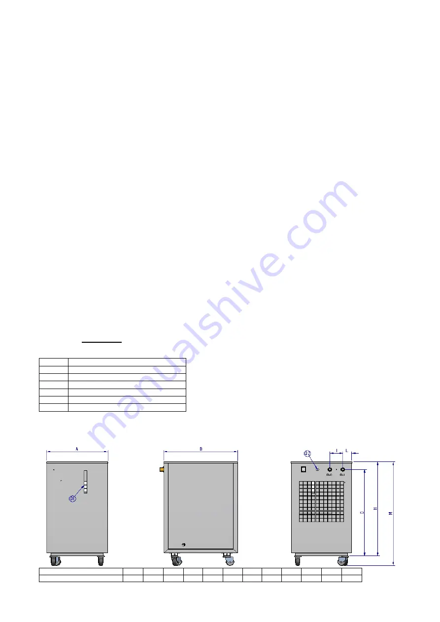
HOUSING
Legend for all the following housing versions:
1
Level
2
Power supply
3
Temperature controller
04I
Cooling medium inlet
04O
Cooling medium outlet
05I
Cooling water condenser inlet (*)
05O
Cooling water condenser outlet (*)
(*) in water-cooled chillers
MODELS: CHW 09
MODELS
A
B
H
C
D
E
F
G
I
L
M
(Ø)
CHW 09
375
450
630
/
580
/
/
/
80
55
/
1/2”
Summary of Contents for CHG 08
Page 40: ...710 1760 00 04 05 22 05 2014 40 CHW 20 25 CHO 10 cST CHG 20 25 5 EN 60204 EN 378 2...
Page 41: ...710 1760 00 04 05 22 05 2014 41 HFC CE 842 2006 3 3 1 3 2 C CND EVA HP LP...
Page 42: ...710 1760 00 04 05 22 05 2014 42 MHP MLP PV R V a 2 5 b VE 2 5 MOP IAF 3 3 MF P...
Page 43: ...710 1760 00 04 05 22 05 2014 43 BP BPM CAA EV 1 1 VNR FL LVE RA TD VNR EV 1 2 3...
Page 44: ...710 1760 00 04 05 22 05 2014 44 1 2 3 4 5 6 7 3 4 ALR...
Page 65: ...710 1760 00 04 05 22 05 2014 65 CHW 682 CHW 3652 CHG 225 CHG 365 6 4 1 2 0 0 5 2 1...
Page 67: ...710 1760 00 04 05 22 05 2014 67 5 6 8 9 10 3 20 15...


