Cod. 710.0138.01.00 Rev04A
– 03.2017
© Copyright 2017 OMI Srl - All rights reserved
4
– 12
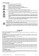
2.4 INSTALLATION
Before attempting any installation operation, make sure that
No parts of the air system are under pressure.
No parts of the system are electrically powered.
Tubing to be connected to the dryer are free of impurities.
The pipes to be connected to the dryer does not weigh on the device.
All interconnecting piping has been tightened.
After having verified the points listed above, you can proceed to the installation of the machine.
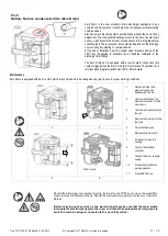
1. Connect the dryer to the compressed air lines. If not already existing, we suggest to install a by-pass allowing to
isolate the machine from the plant, thus to facilitate eventual maintenance operations.
2. Perform the electrical connection in accordance with any local laws and regulations after reviewing the dryer
electrical specifications and wiring diagram. In particular, if the power cord has no plug, install a disconnecting
device ( ED 18-260 ).
3. Check the condensate drainage assembly, and connect the drain flexible hose to the draining line, keeping in
mind that
the condensate separated by the dryer may contain oil, therefore, in order to dispose of it in
compliance with the local rules in force, we suggest installing a water-oil separator having adequate
capacity.
4.
Power the dryer after having checked that the nominal voltage and line frequency are constant and matching the
nominal values of the machine.
The user must provide the installation with an adequate line protection and
a ground terminal complying with the electrical rules locally in force.
In order to optimise the use of the dryer, we suggest to place it in such a way that all the control instruments of the machine
will result easily visible.
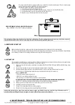
A suitably sized prefilter must be installed before the dryer. Failure to install and maintain a proper prefilter will
void the dryer warranty. The rating for this filter must be at least 10 micron.
It is necessary for the user to install a protective device (a safety accessory) to protect the equipment under
pressure from the risk of exceeding the maximum allowable pressure (PS); it is necessary to install a protective
device to protect the equipment at high temperature from the risk of exceeding the maximum allowable
temperature.
3. START UP
Ensure that the dryer is by−passed, or there is no load on the cooler.
Switch on the main electrical isolation switch (if present). The control panel will show the message OFF, indicating that the line and
control voltages are available.
Start sequence
The dryer will initially start by pressing and holding the local ON/OFF button. The start sequence will progress only if there are no active
alarms. The compressor motor will start AFTER 120 SECONDS. The fan motor will start simultaneously with the compressor for ED225-
660 models, after 30 seconds for smaller models.
Mod.ED780-1000: the fan motor is controlled only by the fan pressure switch.
Stop sequence
The dryer can be stopped locally from the control panel. After having pressed the ON/OFF switch for 1 second, the compressor and the
fan motor (only the compressor on ED780-1000) keep on running for further 10 seconds in order to re-balance the internal pressures. The
dryer can be also stopped due to an
alarm or energy saving condition (ESA or ES2). Any alarm will de−energize the compressor, fan
motor can still running (only on ED18-660), it depends on the type of alarm (see Display indications chapter). If the shutdown is due to an
alarm, a message will blink on display indicating the reason for the shutdown. Energy saving condition (ESA or ES2) occurs when the
dew point stands below the set value for a long time in order to save energy and avoid heat exchanger freezing. This situation can
happen when ambient temperature is low and there is no compressed air load.
Mod.ED780-1000: the fan motor is controlled only by the fan pressure switch.
Variable speed fan control (Mod. ED18-660)
A patented microprocessor allows to adjust dryer’s cooling capacity by changing the fan motor speed. If the dew point is greater than
the set value, the fan speed is increased, if the dew point is smaller than the set value, the fan velocity is decreased. The range can be
from 0 to 100% and the higher is the fan speed, the faster the fan LED blinks, you can read the exact value by pressing the UP button.
If the velocity is 100% you will read FL (Full Load). Under load standard condition the fan speed is usually at 100%, if there is no load
the fan velocity can oscillate between 0 and 20%.
In models ED225-660
, in order to adjust the greater dryer’s cooling capacity, a hot gas by-pass valve cooperates with the variable
speed system.
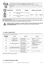
3.1 CONTROL PANEL
The dryers are provided with an electronic control system. All adjustments and resets can be performed by means of the digital panel
located on the front of the dryer. The control panel is composed of 5 keys (ON/OFF, TEST, SET, DOWN and UP) and a 3 digit display,
with three signalling LEDs indicated by icons (PIC 1)


