ENGLISH
Cod. 710.0151.01.00 Rev0B – 08.2012
5 - 66
2.2 INSTALLATION SITE
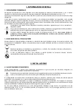
While preparing a proper site for the installation of the dryer, please take into account the following
requirements
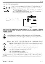
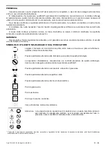
The machine must be protected from atmospheric agents and not directly exposed to sun light.
A seating base flat and capable to hold the weight of the machine.
Ambient temperature complying with the nominal data of the dryer.
A clean, dry and without forced draft (we suggest to blow the warm air outside the installation site).
Make sure to leave sufficient clearance around the dryer in order to allow an adequate cooling of
the machine and for maintenance and/or control operations
.
The incoming air must be free from smoke or flammable vapours which could lead to explosion or fire
risks.
2.3 INSTALLATION
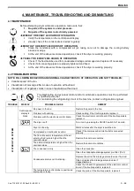
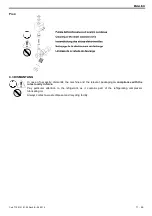
Before attempting any installation operation, make sure that
No parts of system are under pressure.
No parts of the system are electrically powered.
Tubing to be connected to the dryer are impurities free.
After having verified the points listed above, you can proceed to the installation of the machine.
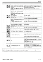
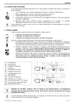
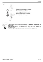
1. Connect the dryer to the compressed air lines indicated in the diagrams below. If not already
existing, we suggest to install a by-pass allowing to insulate the machine from the plant, thus to
facilitate eventual maintenance operations.
2. Check the condensate drainage assembly, and connect the drain flexible hose to the draining line,
keeping in mind that the condensate separated by the dryer contains oil particles, therefore,
in order to dispose it in compliance with the local rules in force, we suggest a water-oil
separator having adequate capacity.
3. Power the dryer after having checked that the nominal voltage and line frequency are constant
and matching the nominal values of the machine. The user must provide the installation with
an adequate line protection and a ground terminal complying with the electrical rules
locally in force.
In order to optimise the use of the dryer, we suggest to place it in such a way that all the control
instruments of the machine will result easily visible.
Installing a ceramic pre-filter on the air inlet of the dryer, this will be better protected from eventual solid
particles, as it prevents the accumulation of oily materials on the heath exchangers.
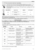
1
Air Compressor
2
Aftercooler
3
Condensate Separator
4
Receiver
5
Automatic Drain
6
Ceramic Prefilter 10
μ
7
Dust Filter 5
μ
8
Dryer
9
Solenoid drain valve
10
Coalescing Filter 1
μ
– 0.1 mg/m
3
11
Coalescing Filter 0.01
μ
– 0.01 mg/m
3
12
Activated carbon filter 0.003 mg/m
3
13
Water/Oil Separator
Summary of Contents for EL 36
Page 2: ......
Page 50: ...Cod 710 0151 01 00 Rev0B 08 2012 48 66...
Page 51: ...Cod 710 0151 01 00 Rev0B 08 2012 49 66 1 1 1 3 C IP 42 1 2 2 2 1 8 50 90 12...
Page 56: ...Cod 710 0151 01 00 Rev0B 08 2012 54 66 4 4 1 1 2 40 200 2000 4 2 ESA 1 ON OFF 2 3 C8 C9...
Page 57: ...Cod 710 0151 01 00 Rev0B 08 2012 55 66 1 C8 C9...
Page 58: ...Cod 710 0151 01 00 Rev0B 08 2012 56 66 4 4 3...
Page 64: ...Cod 710 0151 01 00 Rev0B 08 2012 62 66 Cod 714 0170 07 00 Rev 00 EL 280 340 230V 1Ph 50Hz...
Page 69: ......


