background image

5

Connection, access & initial setup

5.1 Connecting OTMC 100 to an Ethernet network

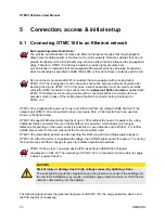
Note regarding network switches:

The precise synchronization of clocks via Ethernet networks requires that the propagation
delay times for data packets is constant on the entire network. Network switches that do not
provide transparent clock functionality may introduce jitter and thus influence the propagation
delay. Therefore, 

OTMC 100

 will only be able to provide highly accurate time

synchronization in networks that are equipped with network switches providing transparent
clock functionality as specified in IEEE 1588-2008 or that do not have a network switch at all.

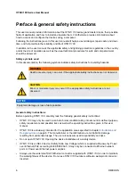
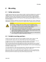
Do not connect conventional RJ45 connectors that are equipped with a locking tab to

OTMC 100

. The locking tab of such connectors cannot be accessed directly anymore after

inserting the plug to 

OTMC 100

. In this case, a small screwdriver must be used to carefully

unlock the RJ45 connector in the socket. Use the 

waterproof RJ45 connector

 supplied with

OTMC 100

 instead or, when using a cable with a conventional RJ45 connector (for test

purposes only!), break off the locking tab at the RJ45 connector before inserting it to

OTMC 100

.

OTMC 100

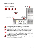
 is supplied with power by Power over Ethernet (PoE) according to IEEE 802.3af. If the

network port 

OTMC 100

 is connected to does not provide PoE, a PoE injector has to be used as

shown in the figure below.

OTMC 100

 supports Ethernet cable lengths of up to 100 m without the need of repeaters. By using

additional media converters the use of optical Ethernet is possible, which allows much longer
distances. Depending on the used variant it is possible to cover distances up to 2000 m. For further
details, please refer to the user manual of the media converters used.

OTMC 100

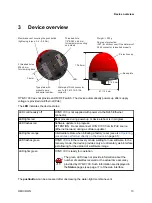
 automatically powers up after inserting the RJ45 plug and providing supply voltage to

OTMC 100

. After the device is supplied with voltage, the LED first lights up red for approx. 15 s during

the boot process and then changes to green to indicate operational readiness.

OTMC 100

 is a class 1 powered device (PD) as defined in IEEE 802.3af (power

consumption < 3.84 W). The network port 

OTMC 100

 is connected to must be able to supply

a class 1 powered device.

CAUTION

Risk of injury or damage due to high voltages caused by lightning stroke.

The local lightning protection regulations and the protection concept of the building and
the electrical installation may require a suitable surge protection device for the Ethernet
network cable leading into the building.


The following figure shows the general arrangement of 

OTMC 100

, the surge protection device and

the PoE injector (if necessary).

OTMC 100 Series User Manual

20

OMICRON

Summary of Contents for OTMC 100

Page 1: ...Smart Measurement Solutions OTMC 100 User Manual...

Page 2: ...user manual The user is responsible for every application described in this user manual and its results OMICRON electronics explicitly exonerates itself from all liability for mistakes in this manual...

Page 3: ...Next steps to set up OTMC 100 25 6 Operating OTMC 100 27 6 1 Operating procedures performed via the web interface 27 6 1 1 Viewing the GPS PTP NTP and network status 27 6 1 2 Defining a password 27 6...

Page 4: ...7 4 Tools 77 7 4 1 Device Control page 78 7 4 2 Software Update page 79 7 4 3 Configuration Management page 80 8 Automation interface 81 8 1 Access 81 8 2 Configuration 81 9 OMICRON Device Link 82 9 1...

Page 5: ...antenna Increase the separation between the equipment and receiver Connect the equipment into an outlet on a circuit different from that to which the receiver is connected Consult the dealer or an ex...

Page 6: ...e not observed NOTICE Equipment damage or loss of data possible General safety instructions Before operating OTMC 100 carefully read the following general safety instructions OTMC 100 may only be used...

Page 7: ...For outdoor installation always use a shielded Ethernet cable The cable shield has to be connected to the shield of the Ethernet connectors Preface general safety instructions OMICRON 7...

Page 8: ...0p Time reference for use in the electrical power industry In addition to the IEEE 1588 2008 default profiles OTMC 100p also supports the following profiles used in the electric power industry Power p...

Page 9: ...eady for PTP OTMC 100 is able to simultaneously operate as NTP server and PTP grandmaster clock The following features are supported by the OTMC 100 software Time IEEE 1588 2008 version 2 support Defa...

Page 10: ...on via SSH and XML files SNMP for IEEE C37 238 2011 Failsafe software upgrades in the field OTMC 100 series products are exclusively intended for the applications stated in this chapter Any other use...

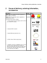
Page 11: ...kit for mast diameters of 25 to 70 mm see OL000350 for details 1 waterproof RJ45 connector 1 standard Ethernet patch cable 3 m 1 OTMC 100 Quick Start Guide printed 1 CD ROM containing the OMICRON Dev...

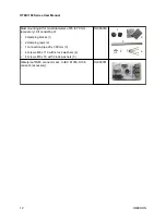
Page 12: ...clamping blocks 1 2 clamping jaws 2 1 connection pipe 20 x 300 mm 3 4 screws M6 x 110 with 4 lock washers 4 4 screws M6 x 16 with 4 lock washers 5 OL000350 1 2 3 4 5 Waterproof RJ45 connector acc to I...

Page 13: ...lights red Boot process during power up or device reboot is in progress LED flashes red Software update is in progress ATTENTION Do not disconnect OTMC 100 from its PoE source Ethernet network during...

Page 14: ...device reboot Initiate a factory reset to reset the device configuration to the factory defaults for example if you forgot your password Please refer to Operating procedures performed directly on the...

Page 15: ...ction device for the Ethernet network cable leading into the building For outdoor installation always use a shielded Ethernet cable The cable shield has to be connected to the shield of the Ethernet c...

Page 16: ...of GPS signals under most conditions This mounting position provides direct view to the sky in a range of nearly 180 The view is only partly hindered and there is negligible danger of reflections tha...

Page 17: ...4 fastening screws M6 x 16 with lock washers 1 connection pipe 20 x 300 mm Proceed as follows Assemble the mast clamp and attach it to the mast as shown in the figure The mast clamp is suitable for ma...

Page 18: ...t to the RJ45 connector on the base plate of OTMC 100 Use suitable cable ties to fasten the Ethernet network cable to the connecting pipe and the mast Always use the waterproof RJ45 Ethernet connector...

Page 19: ...mm deep Make sure not to screw in the grub screw too deep Assemble the delivered waterproof RJ45 connector to the Ethernet cable according to the accompanying assembly instructions and insert it to th...

Page 20: ...oE according to IEEE 802 3af If the network port OTMC 100 is connected to does not provide PoE a PoE injector has to be used as shown in the figure below OTMC 100 supports Ethernet cable lengths of up...

Page 21: ...E injector Surge protection device Mains The following figure shows a typical network with one OTMC 100 a network switch providing transparent clock functionality and several PTP slaves Network switch...

Page 22: ...Microsoft Edge Mozilla Firefox 20 or higher or Google Chrome version 31 or higher If you are accessing OTMC 100 from a Mac or Linux operating system supporting zeroconf you can access the web interfa...

Page 23: ...t the device cannot be accessed Click the OTMC 100 entry and select Configure IP OMICRON Device Link will then display an IP configuration page In this page select Use the following IP address and ent...

Page 24: ...rt page of the OTMC 100 web interface is displayed 8 Proceed with section Next steps to set up OTMC 100 on page 25 in order to configure OTMC 100 according to your needs OTMC 100 Series User Manual 24...

Page 25: ...ply your settings The most important PTP settings are a PTP profile General Settings pane All PTP devices that should synchronize to each other must use the same profile Use the Default E2E or Default...

Page 26: ...tificate pane in section Security configuration page on page 58 for more detailed information d In the Services field select whether you want to allow access to your OTMC 100 via the web interface Web...

Page 27: ...e page 37 showing the information 6 1 2 Defining a password If no password is defined for accessing OTMC 100 a corresponding note is displayed on the Overview page providing the possibility to directl...

Page 28: ...update If the check box is selected the user specific configuration settings are kept during the software update 5 Click the Update button to start the software update 6 The update process may take up...

Page 29: ...settings and the log file It thus provides important information for the technical support in case of problems 1 Click the Tools icon in the navigation bar of the web interface 2 Click the Device Con...

Page 30: ...r exporting the system log file The log file contains all events logged by the system Therefore it may be helpful for the technical support of OMICRON in case of problems Which types of events are act...

Page 31: ...t forget to reinsert the membrane vent in order to restore watertightness Tighten the membrane vent with a tightening torque of 0 6 to 0 8 Nm Membrane vent detached Pushbutton LED Pushbutton 6 2 1 Per...

Page 32: ...sary if you forgot your password for example 1 Press the pushbutton and keep it pressed 2 The LED goes off 3 After approx 5 s the LED lights up orange Keep the button pressed and wait until the LED li...

Page 33: ...f the help system for the web interface Click Support in the top right corner to open the contact information page providing OMICRON contact addresses and information how to contact the technical supp...

Page 34: ...dditional Log Viewer page shows all events logged in the internal log file Configuration see page 54 Use the Configuration pages to view and configure the network security PTP and NTP settings You can...

Page 35: ...n Status GPS Displays the current GPS status of OTMC 100 Possible states are Locked holdover unlocked See GPS status page on page 38 for more information PTP Displays the current PTP status of OTMC 10...

Page 36: ...matically by a IPv4 DHCP server if available in the network or the OTMC 100 itself The IPv4 address can also be set manually by the user See also Network configuration page on page 55 IPv6 address Dis...

Page 37: ...ble GPS see page 38 PTP see page 39 NTP see page 47 Network see page 50 Log Viewer see page 53 Some elements provide an edit hyperlink Click this hyperlink to directly open the corresponding configura...

Page 38: ...tion Satellites visible Displays the number of satellites OTMC 100 can see in the sky Satellites usable Displays the number of satellites from which OTMC 100 can receive signals with sufficient qualit...

Page 39: ...Position Displays the position coordinates latitude and longitude in degrees minutes and seconds and the height in meters and feet 7 2 2 PTP status page The OTMC 100 web interface OMICRON 39...

Page 40: ...ster clock in the network according to the BMCA and is thus used as time reference PTP grandmaster clock Passive Another PTP clock in the network is the best master clock according to the BMCA e g has...

Page 41: ...gMinPdelayReqInterval in IEEE 1588 2008 Only available for profiles Default P2P Power C37 238 2011 Power C37 238 2017 and Power utility 61850 9 3 2016 This parameter is set in the PTP configuration se...

Page 42: ...02 1Q VLAN tag This value represents the PCP Priority Code Point field 3 bits within the TCI Tag Control Identifier See IEEE C37 238 2011 clause 5 6 Only available for PTP profile Power C37 238 2011 O...

Page 43: ...100 is set to a constant value that was determined from laboratory observations Priority 1 Priority 2 Displays the priority values of OTMC 100 To each PTP master clock two priority values Priority 1...

Page 44: ...he network or domain see IEEE 1588 2008 clause 7 6 2 4 The value of the Grandmaster clock class parameter is automatically set by the current grandmaster clock depending on the source of time that is...

Page 45: ...racy See IEEE C37 238 2011 clause 5 13 Only available for PTP profile Power C37 238 2011 OTMC 100p only This parameter is set in the PTP configuration see page 62 Network time inaccuracy ns Displays t...

Page 46: ...6 Frequency traceable True indicates that the frequency determining the timescale currently distributed in the network or domain is traceable to a primary reference for example to GPS see IEEE 1588 20...

Page 47: ...ion for the local driver Internal pane as well as for the external servers and the broadcast multicast servers configured in the NTP configuration see page 69 External and Broadcast panes Refer to the...

Page 48: ...exceeded Association timeout Step time change Interface has changed Selection Displays the current selection status of the peer NTPQ x o Description Discarded not valid Discarded intersection Discard...

Page 49: ...for a detailed description of the displayed information 7 2 3 3 Broadcast pane The Broadcast pane displays the Host the Reference ID the Stratum and the Poll interval for each broadcast multicast serv...

Page 50: ...age The Network status page shows detailed network settings of OTMC 100 in three panes For information how to configure the network settings see Network configuration page on page 55 OTMC 100 Series U...

Page 51: ...ame in the Network configuration 7 2 4 2 IPv4 pane The IPv4 pane displays the IPv4 specific configuration settings of OTMC 100 The IPv4 configuration is set in the Network configuration see page 55 Co...

Page 52: ...Autoconfiguration SLAAC but the user manually specified possible DNS servers in the Network configuration see page 55 IP address Displays the currently assigned IPv6 address of OTMC 100 Network mask D...

Page 53: ...debug messages information etc are displayed in gray Click Clear View to delete the messages displayed in the Log Viewer window This does not clear the log file Re opening the Log Viewer will again d...

Page 54: ...ation The following configuration pages are available Network see page 55 Security see page 58 PTP see page 62 NTP see page 69 Log Notification see page 72 SNMP see page 75 OTMC 100 Series User Manual...

Page 55: ...Domain name If a DHCP server is available in the network OTMC 100 receives the domain name from the DHCP server The domain name can also be set manually by the user for example omicron at Name in Devi...

Page 56: ...our needs IPv6 disabled IPv6 is switched off IPv6 static IP address Select Static to set the IP address manually The page then enables the fields for entering the IP address the Gateway address and th...

Page 57: ...he check box to enable the service used by OMICRON Device Link or Device Browser to automatically detect OMICRON devices in the network Zeroconf Select the checkbox to enable detection of OTMC 100 dev...

Page 58: ...cess etc The password is case sensitive and must have at least 6 characters letters figures or special characters Confirm password Repeat your password for confirmation Access Select Anonymous if you...

Page 59: ...example performed to change the configuration Deselecting all options will minimize potential points of attack and thus provide highest security Click the corresponding check box to select or deselect...

Page 60: ...ssage will appear because OTMC 100 does not have a valid certificate To avoid such messages it is necessary to provide OTMC 100 with such a certificate There are two possible ways Generating a certifi...

Page 61: ...trusted connection message when accessing OTMC 100 Proceed as follows to generate a self signed certificate 1 Enter the required information to the fields Domain name E mail address Country code e g A...

Page 62: ...nded for application in power system environments that use the Precision Time Protocol according to the IEEE Std C37 238 2011 IEEE Standard Profile for Use of IEEE 1588 2008 Precision Time Protocol in...

Page 63: ...his field to specify the priority values To each PTP master clock two priority values Priority 1 and Priority 2 may be assigned by the user If more than one PTP grandmaster clock is available in the n...

Page 64: ...This field is initialized by the grandmaster to the grandmaster time inaccuracy plus the source time inaccuracy and then incremented by TCs and BCs Only available for PTP profile Power C37 238 2017 O...

Page 65: ...r PTP packets The Power profile according to IEEE C37 238 2011 requires an IEEE 802 1Q VLAN tag However for compatibility reasons it is possible to disable it Only available for PTP profile Power C37...

Page 66: ...example a value of 0 will result in an interval of 1 second 20 Note Minimum pdelay request interval 2Log min pdelay request interval seconds see IEEE 1588 2008 clause 8 2 5 4 5 Log min delay request i...

Page 67: ...ress FF02 6B is used For all other messages the IPv6 multicast address FF0X 181 is used where the value of X is selected by the IPv6 multicast scope setting All clocks in a network that shall be synch...

Page 68: ...TIME_OFFSET_INDICATOR TLV Text of max 10 characters See displayname and ALTERNATE_TIME_OFFSET_INDICATOR in IEEE 1588 2008 clause 16 3 3 7 and IEEE C37 238 Current offset Use this field to specify the...

Page 69: ...hronizes to the time source Select the corresponding pane to specify your NTP configuration settings Click the Save button to save and apply your NTP configuration specified in the individual tabs to...

Page 70: ...er of 2 i e in 2x seconds For example if you enter a value of 5 OTMC 100 will poll the NTP time server every 32 seconds 25 Possible values 4 to 17 resulting in an interval between 16 and 131072 second...

Page 71: ...etween 16 and 131072 seconds IPv4 Multicast Select the Enabled check box to enable the sending of IPv4 multicast messages containing NTP time information If enabled enter the IPv4 multicast address in...

Page 72: ...ile that can be viewed using the Log Viewer page see page 53 in the Status section Local log and IPv4 syslog server and Local log and IPv6 syslog server Logging is performed to the internal log file a...

Page 73: ...and port number of the SMTP e mail server Sender e mail Use this field to specify the e mail address of OTMC 100 Recipient e mail Use this field to specify the recipient e mail address for the event n...

Page 74: ...e Notification if OTMC 100 left the PTP master state because another grandmaster clock provides more accurate time information than OTMC 100 Faulty Notification if PTP time information is no longer av...

Page 75: ...d in the individual tabs to OTMC 100 A MIB file is required for proper representation of OTMC 100 settings in SNMP clients Refer to the Device Control page see page 78 of the Tools section to download...

Page 76: ...t Disabled from the list box to disable this function Or select Trap to send a trap message or Inform to send an inform request to the SNMP manager in case of an occurring event Such messages can only...

Page 77: ...7 4 Tools The following pages are available in the Tools section Device Control see page 78 Software Update see page 79 Configuration Management see page 80 The OTMC 100 web interface OMICRON 77...

Page 78: ...eset can also be performed using the pushbutton on the device System snapshot Click the Download button to download a system snapshot containing all configuration settings and the log file The system...

Page 79: ...tomatically reset the device configuration to the factory defaults after a software update Update button Click the Update button to start the software update The update process may take up to ten minu...

Page 80: ...d in the field after selecting it in the file open dialog Click the Save button to upload and save the configuration file to OTMC 100 Download XML configuration Click the Download button next to XML c...

Page 81: ...here passwords are not transmitted in plain text Note that the TFTP and FTP services can also be disabled if not needed The log and configuration files are located in the home directory of user omicro...

Page 82: ...page not be displayed automatically a few seconds after the CD has been inserted into the CD ROM drive change to the Windows Explorer and double click autorun exe on the CD ROM 3 Follow the instructi...

Page 83: ...bnet mask field to automatically fill a subnet mask and then click Apply to connect to your OTMC 100 Or Click the Add device button and enter the IP address assigned to your OTMC 100 3 A green vertica...

Page 84: ...according to IEEE 802 3af Power consumption 2 W GPS performance 12 channel GPS receiver Frequency 1575 42 MHz L1 band 10 2 Mechanical specifications Characteristic Specification Dimensions Overall he...

Page 85: ...B EN 61326 1 2013 FCC Subpart B of Part 15 Class B EMC immunity EN 55024 2010 EN 61326 1 2013 EN 62305 4 2010 Certified safety standards Safety IEC 60950 1 2005 2 Ed A1 2009 IEC 60950 22 2005 Certifi...

Page 86: ...licenses To view the license information on the Open Source software used in OTMC 100 please launch the OTMC 100 web interface and click the License Information hyperlink in the bottom right corner Th...

Page 87: ...ame System MIB Management Information Base NTP Network Time Protocol P2P Peer To Peer PoE Power over Ethernet according to IEEE 802 3af PTP Precision Time Protocol RFC Request for comment SCP Secure C...

Page 88: ...t is one of our top priorities At our technical support hotline you can reach well educated technicians for all of your questions Around the clock competent and free of charge Make use of our 24 7 int...

Page 89: ...ENU 1066 05 01...

Reviews: