53
Frequency Sweep Mode
Since the output of the DUT (quartz filter) is connected to the channel 2 input,
the measured impedance is the quartz impedance plus the 50
Ω
input
impedance of the
Bode 100
.
For an idle quartz, the trace should be nearly symmetrical against the real axis.
The reason why it is not is as follows: We have used a cable to connect the
quartz to the
Bode 100
and therefore we measure a phase shift of the reflected
voltage (twice the shift of the cable itself). We can remove this unwanted phase
shift by using the
Impedance/Reflection
calibration. By calibrating the
Bode 100
we move the
Impedance/Reflection
reference plane to the end of the
cable connected to the input of the DUT.
5.2 Impedance/Reflection
Calibration
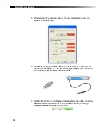
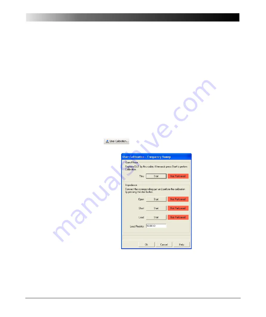
Now we perform the
Impedance/Reflection
calibration. This type of calibration
is also described in 6.4 "Calibration in the Impedance/Reflection Mode" on
page 66.
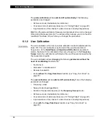
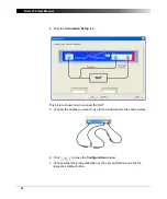
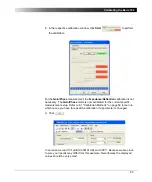
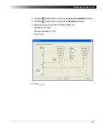
1. Click the
toolbar button to open the calibration window.
Summary of Contents for Bode 100
Page 1: ...Bode 100 User Manual...
Page 6: ...Bode 100 User Manual 6 This page intentionally left blank...
Page 12: ...Bode 100 User Manual 12 This page intentionally left blank...
Page 14: ...Bode 100 User Manual 14 This page intentionally left blank...
Page 72: ...Bode 100 User Manual 72 This page intentionally left blank...
Page 81: ...81 Advanced Functions Figure 7 12 Measured curve with sweep settings copied from the zoom area...
Page 98: ...Bode 100 User Manual 98 This page intentionally left blank...
Page 100: ...Bode 100 User Manual 100 This page intentionally left blank...
Page 104: ...Bode 100 User Manual 104 This page intentionally left blank...

