background image

61

Calibrating the Bode 100

Hint:

Use the user calibration for the highest accuracy of measurement results 

or if you want to compensate for highly frequency selective components in your 
measurement setup such as narrow-band measurement probes.

6.1.3    Hierarchy of Calibration Methods

The 

Bode 100

 allows you to activate the user calibration and the probe 

calibration at the same time (see Figure 6-1: "Activating user and probe 
calibration"
 below).

Figure 6-1:
Activating user and 
probe calibration

If both the user calibration and the probe calibration are activated, the more 
accurate user calibration is used. If measurement parameters are changed and 
the user calibration becomes void the 

Bode 100

 switches automatically to the 

probe calibration; the user calibration is then switched off until the 

Bode 100

 is 

recalibrated.

6.2     Calibration in the Gain/Phase Mode (Internal 

Reference)

For calibrating the 

Bode 100

 in the 

Gain/Phase

 mode you find a practical 

example in 3.3 "Example: Gain/Phase Measurement" on page 24.

Note:

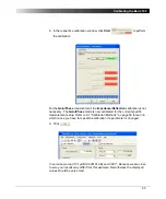
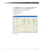
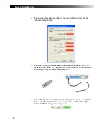
The probe calibration is performed in the same way as the user 

calibration.

Summary of Contents for Bode 100

Page 1: ...Bode 100 User Manual...

Page 2: ...ht to make changes at any time to the technology and or configuration without announcement OMICRON electronics is not to be held liable for statements and declarations given in this User Manual The us...

Page 3: ...ng the Bode 100 with the PC 13 3 Gain Phase Mode 15 3 1 Basics 20 3 1 1 Internal Reference Connection 21 3 1 2 External Reference Connection 21 3 2 Choosing the Reference Connection 22 3 3 Example Gai...

Page 4: ...onfiguration 73 7 1 2 Exporting Measurement Data 74 7 2 Advanced Display Options 76 7 2 1 Gain Phase and Impedance Reflection Mode Context Menu 76 7 2 2 Frequency Sweep Mode Context Menu 78 7 3 Advanc...

Page 5: ...urement techniques and the use of PC based applications running under a Windows environment Conventions and Symbols Used In this manual the following symbol indicates paragraphs with special safety re...

Page 6: ...Bode 100 User Manual 6 This page intentionally left blank...

Page 7: ...rcuits An internal bridge allows performing measurements by just connecting the device under test DUT to the Bode 100 s source Frequency Sweep measurements In addition to single frequency measurements...

Page 8: ...Manual 8 1 2 Block Diagram Figure 1 1 Block diagram CH 2 receiver CH 1 receiver DDS signal source Microcontroller CH 1 ADC CH 2 ADC DC power converter DC power input USB 1 1 interface CH 1 INPUT CH 2...

Page 9: ...rse power at the OUTPUT connector The Bode 100 provides the following connectors OUTPUT signal source output on the front panel CH 1 INPUT channel 1 input on the front panel CH 2 INPUT channel 2 input...

Page 10: ...Bode 100 complies with the following standards Table 1 1 Standard compliance Standard Description IEC 61326 Class B equipment Performance criterion B EMC requirements Universal Serial Bus USB Specifi...

Page 11: ...power supply including mains input plugs for different national standards Test objects on a PCB Quartz filter IF filter USB cable 4 BNC 50 cable m m BNC straight adapter f f BNC T adapter f f f BNC s...

Page 12: ...Bode 100 User Manual 12 This page intentionally left blank...

Page 13: ...t on page 105 2 2 Powering the Bode 100 Caution Before powering the Bode 100 using a DC power supply not delivered with the Bode 100 check the polarity of its output voltage see 10 2 Power Requirement...

Page 14: ...Bode 100 User Manual 14 This page intentionally left blank...

Page 15: ...See Figure 3 3 Calibration toolbar on page 17 Split bar Drag the split bar to resize the panes Graphical display of measurement results Use the context menu to optimize the display See Figure 3 6 Gra...

Page 16: ...in Phase Selects the Gain Phase measurement mode Impedance Reflection Selects the Impedance Reflection measurement mode Frequency Sweep Selects the Frequency Sweep measurement mode Continuous Measurem...

Page 17: ...SV export options see 7 1 File Operations on page 73 Help Contents Opens the online help About Displays the Bode Analyzer Suite version Open New Save Search and Reconnect Device Device Configuration C...

Page 18: ...ncreases the measurement accuracy Figure 3 5 Gain Phase mode results Set the output source generator frequency Set the output source generator level Select the channel 1 input attenuation Select the c...

Page 19: ...k whether the Bode 100 is powered and connected with your PC and then click the toolbar button to reconnect the Bode 100 Right click in the diagram to open the context menu Use the context menu to opt...

Page 20: ...where S parameter from port i to port j of the DUT transfer function of a two port device depends on the load of the port where is measured voltage at the DUT s output open circuit voltage of the sou...

Page 21: ...14 Eq 3 15 Eq 3 16 Channel 2 Input Resistance 50 High Impedance Eq 3 6 Eq 3 7 Eq 3 8 Eq 3 9 Eq 3 10 of the DUT Eq 3 11 Eq 3 12 Eq 3 13 If you make a through connection from the source to CH 2 0 dB gai...

Page 22: ...lbar button see 3 3 Example Gain Phase Measurement on page 24 By default the Device Configuration tab is selected To connect the reference internally set the marked configuration field as shown below...

Page 23: ...onfiguration field as shown below and then connect the OUTPUT connector to the CH 1 INPUT connector using a cable Note The source signal is externally connected to the channel 1 input behind the 50 so...

Page 24: ...of a sinusoidal signal at a certain frequency set bandwidth attenuators and amplitudes of the generator optimize the diagram compensate the connection cables in the Gain Phase mode Question What magn...

Page 25: ...ered properly and then click the toolbar button 2 Click the toolbar button to configure the Gain Phase mode 3 Set CH2 50 ON click on switch as shown SOURCE 10 7 MHz Receiver bandwidth 10 Hz ATTN 1 cha...

Page 26: ...t the DUT Hint Use the box to set the voltage ratio when a probe is used instead of cable connection see 7 3 Advanced Sweep Options on page 88 5 Connect the test object IF filter to the Bode 100 as sh...

Page 27: ...r has a magnitude of 31 79 dB at 10 7 MHz Your result may differ because each IF filter is slightly different The phase readout is not the value you want to measure because it is the sum of the phase...

Page 28: ...C straight adapter f f 2 Click the toolbar button to open the calibration window 3 In the User Calibration Gain Phase window click Start The calibration takes only a few seconds The Gain Phase mode is...

Page 29: ...g the calibration For more information see 6 Calibrating the Bode 100 on page 59 Result The transfer function of the IF filter has a magnitude of 31 82 dB and a phase shift of 57 9 at 10 7 MHz Again y...

Page 30: ...frequency set bandwidth attenuators and amplitude of the generator optimize the diagram compensate the connection cables in the Gain Phase mode As OMIfuzius said Only applied knowledge changes the wor...

Page 31: ...8 Reference resistance Set the reference resistance see 4 1 1 General Formulas on page 32 Results Select the result format and get result values See Figure 4 2 Impedance Reflection mode results on pag...

Page 32: ...mittance reflection coefficient reference resistance reference conductance Note The reference resistance can be set in the Measurement area of the Impedance Reflection mode window Select the output fo...

Page 33: ...s capacitance series inductance The basic formulas for the parallel equivalent circuit are Eq 4 9 Eq 4 10 If Eq 4 11 If Eq 4 12 where parallel resistance parallel reactance parallel inductance paralle...

Page 34: ...t circuits are displayed according to the IEC International Electronic Commission or ANSI American National Standards Institute standards as shown below Figure 4 3 Resistor and inductor according to A...

Page 35: ...r is a measure of the inductor s and capacitor s efficiency The higher the factor of a capacitor or inductor the closer the capacitor inductor approaches the behavior of an ideal lossless component Th...

Page 36: ...number of your Bode 100 on the lower right side of the status bar then your Bode 100 is working properly 2 Click the toolbar button to switch to the Impedance Reflection mode 3 If necessary adjust you...

Page 37: ...37 Impedance Reflection Mode 4 Click the toolbar button to configure the Impedance Reflection mode 5 Set SOURCE 10 7 MHz Receiver Bandwidth 10 Hz Level 0 dBm...

Page 38: ...nt In the Impedance Reflection mode the channel 1 and channel 2 inputs are not used Consequently the External Probe boxes are unavailable 7 Connect the output of the Bode 100 to the DUT IF filter inpu...

Page 39: ...iagrams and then click Optimize 10 View the results Result The measured values of the IF filter at 10 7 MHz are Reflection coefficient 31 1 dB Impedance nearly 50 Hint If you cannot see the result the...

Page 40: ...nd that you are using real components with a factor on their own For information on how to calibrate the Bode 100 in the Impedance Reflection mode see 6 4 Calibration in the Impedance Reflection Mode...

Page 41: ...4 1 Impedance Reflection mode window on page 31 Diagram setup See Figure 5 5 Diagram setup on page 44 Sweep settings Set frequency sweep See Figure 5 2 Sweep settings on page 42 Cursor settings Set cu...

Page 42: ...p stop frequency Set the frequency sweep center frequency Set the frequency sweep span Click Linear or Logarithmic to select the respective scale of measurement points Set the number of measurement po...

Page 43: ...the minimum value on the trace 1 Y axis Data Memory See Data and Memory on page 83 Set the color of trace 2 Click Gain Reflection Impedance or Admittance to select the respective trace 2 measurement...

Page 44: ...p how to use the Frequency Sweep mode of the Bode 100 How to visualize measurement data in a graph set configuration parameters like the input resistor and bandwidth set sweep parameters like start an...

Page 45: ...s What is the attenuation of the quartz filter at the series resonance What is the series resistance Rs of the quartz filter Measurement Procedure 1 Connect the Bode 100 to the PC and start the Bode A...

Page 46: ...left side of the Frequency Sweep mode window ATTN 1 channel 1 input attenuator 10 dB ATTN 2 channel 2 input attenuator 10 dB Receiver bandwidth 30 Hz Level 0 dBm Hint With a narrow receiver bandwidth...

Page 47: ...t the DUT quartz filter Hint Use the box to set the voltage ratio when a probe is used instead of cable connection see 7 4 Using Probes on page 92 6 Connect the quartz filter to the Bode 100 as shown...

Page 48: ...e Sweep area of the Frequency Sweep mode window should now look like below Hint A setting which results in an out of range frequency for any other parameter will be corrected to ensure that all sweep...

Page 49: ...weep Mode 10 Activate both traces and set the parameters as shown below 11 If you have a bigger screen then you can adjust your window size Move the mouse to the lower right corner of the window and d...

Page 50: ...he size of the diagrams In the upper graph you see the gain of the quartz filter You can use the cursors to measure the series and parallel resonance frequencies 12 Select the Cursor 1 and Cursor 2 ch...

Page 51: ...series resonance frequency of 11 998 MHz and an attenuation at the series resonance frequency of 1 47 dB Cursor 2 marks the parallel resonance frequency of 12 025 MHz and an attenuation at the paralle...

Page 52: ...ram format allows an easy translation of any point of the reflection coefficient curve into the corresponding DUT s impedance The cursor values displayed in the Smith chart format are the real and ima...

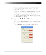
Page 53: ...nd therefore we measure a phase shift of the reflected voltage twice the shift of the cable itself We can remove this unwanted phase shift by using the Impedance Reflection calibration By calibrating...

Page 54: ...dance area of the calibration window After the calibration has been completed the field on the right displays Performed on green background With the measurement settings the calibration may take about...

Page 55: ...tion has been completed the field on the right displays Performed on green background 6 Replace the BNC short circuit with the BNC 50 load 7 Click the Start button next to Load in the Impedance area o...

Page 56: ...the load resistor with an accurate ohmmeter and enter the exact value in the Load Resistor box 9 Click You have done the Impedance Reflection calibration for the Frequency Sweep mode 10 Reconnect the...

Page 57: ...l part measured with cursor 1 The reason is that the reflection measurement circuit sees the quartz filter in series with the 50 termination of the channel 2 input The Trace 2 columns of the table dis...

Page 58: ...figuration parameters like the input resistor and bandwidth set sweep parameters like start and stop frequencies use cursors to read single measurement points calibrate and compensate for the cable Fr...

Page 59: ...of the Bode 100 allows you to change several measurement parameters without the need of recalibration During the probe calibration calibration factors are determined at the factory defined frequencies...

Page 60: ...ase and Impedance Reflection measurement modes the Bode 100 is calibrated at the source frequency In the Frequency Sweep mode the calibration is performed at the exact frequencies specified by the mea...

Page 61: ...igure 6 1 Activating user and probe calibration If both the user calibration and the probe calibration are activated the more accurate user calibration is used If measurement parameters are changed an...

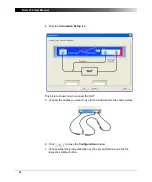
Page 62: ...Gain Phase mode follow the following step by step procedure 1 Connect the Bode 100 and start the Bode Analyzer Suite software Select the Gain Phase mode 2 Click the toolbar button to open the Configur...

Page 63: ...Calibrating the Bode 100 3 Set External reference CH1 Click on the switch symbol CH1 and CH2 50 Click on the switch symbols SOURCE 10 7 MHz Receiver bandwidth 10 Hz ATTN 1 20 dB ATTN 2 20 dB Level 0 d...

Page 64: ...This picture shows how to connect the DUT 5 Connect the cables you want to use for the measurement as shown below 6 Click to close the Configuration window 7 Choose either the probe calibration or the...

Page 65: ...he Gain Phase mode is now calibrated for the current specific measurement setup Refer to 6 1 Calibration Methods on page 59 to learn in which cases you have to repeat the calibration if a parameter is...

Page 66: ...a DUT is connected with a cable the impedance is not measured at the DUT input but at the input of the cable Example Measure the input impedance of the IF filter at the BNC connector of the PCB and n...

Page 67: ...the toolbar button to switch to the Impedance Reflection mode 2 Click the toolbar button to open the Configuration window 3 Because we want to test the 10 7 MHz IF filter set SOURCE 10 7 MHz Receiver...

Page 68: ...nt to use for the measurement to the OUTPUT connector of the Bode 100 Plug the BNC straight adapter on the other end of the cable to have the same reference plane 7 Click the Start button next to Open...

Page 69: ...he calibration window After the calibration has been completed the field on the right displays Performed on green background 10 Replace the BNC short circuit with the BNC 50 load 11 Click the Start bu...

Page 70: ...anual 70 12 Measure the value of the load resistor with an accurate ohmmeter and enter the exact value in the Load Resistor box 13 Click You have done the Impedance Reflection calibration 14 Connect t...

Page 71: ...ery IF filter and measurement setup is slightly different Congratulation In this example you learned the calibration of the Bode 100 in the Impedance Reflection mode How to eliminate the influence of...

Page 72: ...Bode 100 User Manual 72 This page intentionally left blank...

Page 73: ...for repetitive measurement tasks With the equipment configurations stored you can load the respective files for each measurement instead of setting the Bode 100 manually A saved file containing the Bo...

Page 74: ...data all equipment settings are exported into a comma separated file csv This file format can be easily processed by standard spread sheet analysis tools such as Excel Depending on the chosen measure...

Page 75: ...you can chose between different decimal and value separators To select the separators you want to use click Options on the Tools menu and then select the decimal and value separators in the Options di...

Page 76: ...ext menu right click in a diagram in the graphical display 7 2 1 Gain Phase and Impedance Reflection Mode Context Menu The context menu in the Gain Phase and Impedance Reflection mode is shown below F...

Page 77: ...fter releasing the left mouse button the diagram is rescaled to display the zoomed area Figure 7 7 Selecting zoom area To switch off the zoom mode click Zoom Mode on the context menu to cancel the sel...

Page 78: ...s see 7 2 1 Gain Phase and Impedance Reflection Mode Context Menu on page 76 Zoom Mode In the Frequency Sweep mode using the Zoom Mode command you can optimize and reset the X axis and the Y axis sepa...

Page 79: ...X Axis or Y Axis on the context menu and then click Optimize or Reset to optimize or to zoom out respectively the selected axis Copy from Zoom The button allows you to copy the start and stop frequenc...

Page 80: ...ng the Copy from Zoom function the original sweep settings are lost If used the user calibration is switched off too Figure 7 11 Measured curve with initial sweep settings Hint Compare the frequency s...

Page 81: ...81 Advanced Functions Figure 7 12 Measured curve with sweep settings copied from the zoom area...

Page 82: ...er an axis the pointer becomes a double headed arrow Then click the left mouse button to zoom in and the right mouse button to zoom out respectively Figure 7 13 Special zoom function applied on Y axis...

Page 83: ...the following Data to display the current measurement data Memory to display the stored measurement data Data Memory to display the difference between the current and the stored measurement data Data...

Page 84: ...mpare the frequency responses detect even smallest differences between the current and stored measurement data by using the Data Memory display function Question How big is the influence on the measur...

Page 85: ...ashed line 5 In the Display list select Data Memory and then touch the housing of the quartz filter with your finger By doing this you shift the parallel resonance frequency of the filter 6 Mark the n...

Page 86: ...w shows a zoomed diagram showing the effect of touching the quartz filter housing Result Touching the quartz housing shifts the parallel resonance frequency by 506 Hz You might measure different value...

Page 87: ...easurement data Hint The Data Memory function allows you to detect even smallest differences between different parameters of the same component type e g comparison of two quartz filters of the same ty...

Page 88: ...e before using the Copy to Clipboard function DUT Delay Measurement Period In the Configuration window you can find the DUT delay and Measurement period fields Figure 7 15 DUT delay and Measurement pe...

Page 89: ...nput frequency has changed To allow for this waiting time we enter 10 ms in the DUT delay box Figure 7 16 Setting the DUT delay The measurement period is automatically updated When using the same numb...

Page 90: ...ints is required The Bode 100 allows you to set any number of measurement points in the range 10 16501 To set the number of measurement points click in the Number of Points box and then enter the numb...

Page 91: ...91 Advanced Functions To get back a predefined number of measurement points click the corresponding entry in the Number of Points list Figure 7 18 Selecting a predefined number of measurement points...

Page 92: ...and input channel 2 Figure 7 19 Using a probe The use of probes is recommended for the following applications Measurements at points in the DUT circuitry which are not accessible with BNC cables Meas...

Page 93: ...rminated correctly Hint When using a probe with a DUT which requires a 50 termination you can simply connect the BNC 50 load delivered with your Bode 100 to the output of the DUT 3 To obtain accurate...

Page 94: ...aving calibrated the probe start your measurement at any point of the DUT using the probe Congratulation You learned how to use the advanced functions of the Bode 100 How to load and save the equipmen...

Page 95: ...ion and allows quick access of the Bode 100 using OLE compatible controllers such as Excel or programming languages like Visual C This allows simple integration of the Bode 100 into automated measurem...

Page 96: ...shows a typical code segment used to access functions of the Bode Analyzer Automation Interface In this example a Bode 100 unit is searched for and after a device has been found measurement parameters...

Page 97: ...ference available in the Automation subdirectory of the Bode Analyzer Suite directory Congratulation In this chapter you learned basics about the Bode Analyzer Automation Interface got an overview on...

Page 98: ...Bode 100 User Manual 98 This page intentionally left blank...

Page 99: ...Connect the USB cable to the PC and the Bode 100 and check the power supply Then click the Search and Reconnect Device toolbar button to connect the Bode 100 with the PC 9 2 Lost Communication The los...

Page 100: ...Bode 100 User Manual 100 This page intentionally left blank...

Page 101: ...INPUT CH 2 INPUT connectors Input impedance Low or high impedance selectable Low impedance Input impedance 50 High impedance Input impedance 1 M 2 Input capacitance 40 55 pF Connectors BNC Receiver ba...

Page 102: ...ter connector Ground Inner diameter 2 5 mm Outer diameter 5 0 mm Characteristic Absolute Maximum Rating DC power input DC supply voltage 28 V DC supply reverse voltage device does not work 28 V CH 1 I...

Page 103: ...Minimum configuration Pentium 500 MHz 256 MB RAM CD ROM drive Recommended configuration Pentium 1 GHz 256 MB RAM CD ROM drive Interface USB 1 1 or USB 2 0 Operating system Windows 2000 or Windows XP...

Page 104: ...Bode 100 User Manual 104 This page intentionally left blank...

Page 105: ...Africa Middle East OMICRON electronics GmbH Klaus Austria Phone 43 5523 507 333 Fax 43 5523 507 999 Asia Pacific OMICRON electronics Asia Ltd Hong Kong Phone 852 2634 0377 Fax 852 2634 0390 North and...

Page 106: ...106 This page intentionally left blank...

Page 107: ...66 70 CD ROM 11 13 channel measurement 20 reference 20 configuration Frequency Sweep mode 45 47 Gain Phase mode 25 26 Impedance Reflection mode 37 38 connecting with the PC 13 connector CH 1 INPUT 9...

Page 108: ...lane 32 resistance 32 reference connection external 23 internal 22 reflection coefficient 32 S serial equivalent circuit 33 34 35 Service OMICRON Lab address 105 Smith chart 7 45 57 standard complianc...

Reviews: