Bode 100 User Manual
66
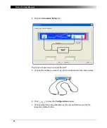
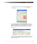
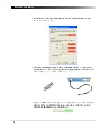
10.The calibration is done and you can connect replace the BNC straight
adapter with your DUT as shown below.
6.4 Calibration in the Impedance/Reflection Mode
If you want to exceed the accuracy of the measurement results in the
Impedance/Reflection
mode you can compensate for the connection setup.
Without calibration the reference plane of the impedance measurements is at
the BNC connector of the source. Therefore if a DUT is connected with a cable,
the impedance is not measured at the DUT input but at the input of the cable.
Example:
Measure the input impedance of the IF filter at the BNC connector of
the PCB (and not the impedance at the input of the cable used for connection of
the filter).
Expected example duration: 20 minutes.
In this example you will learn step by step how to use the calibration of the
Bode 100
in the
Impedance/Reflection
mode.
How to:
• eliminate the influence of the cable
• connect the cable in the open, short and load condition
• connect the DUT
Questions:
• What is the real part of the impedance in
Ω
?
• What is the reflection coefficient in dB?
Summary of Contents for Bode 100
Page 1: ...Bode 100 User Manual...
Page 6: ...Bode 100 User Manual 6 This page intentionally left blank...
Page 12: ...Bode 100 User Manual 12 This page intentionally left blank...
Page 14: ...Bode 100 User Manual 14 This page intentionally left blank...
Page 72: ...Bode 100 User Manual 72 This page intentionally left blank...
Page 81: ...81 Advanced Functions Figure 7 12 Measured curve with sweep settings copied from the zoom area...
Page 98: ...Bode 100 User Manual 98 This page intentionally left blank...
Page 100: ...Bode 100 User Manual 100 This page intentionally left blank...
Page 104: ...Bode 100 User Manual 104 This page intentionally left blank...


