background image

OMICRON

39

Power transformers

5

Power transformers

General

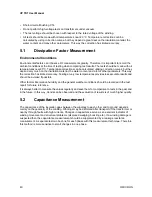
• The transformer must be taken out of service and completely isolated from the power system.
• The proper grounding of the transformer tank has to be checked.
• All bushing high-voltage terminals must be isolated from the connection lines.
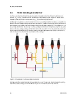
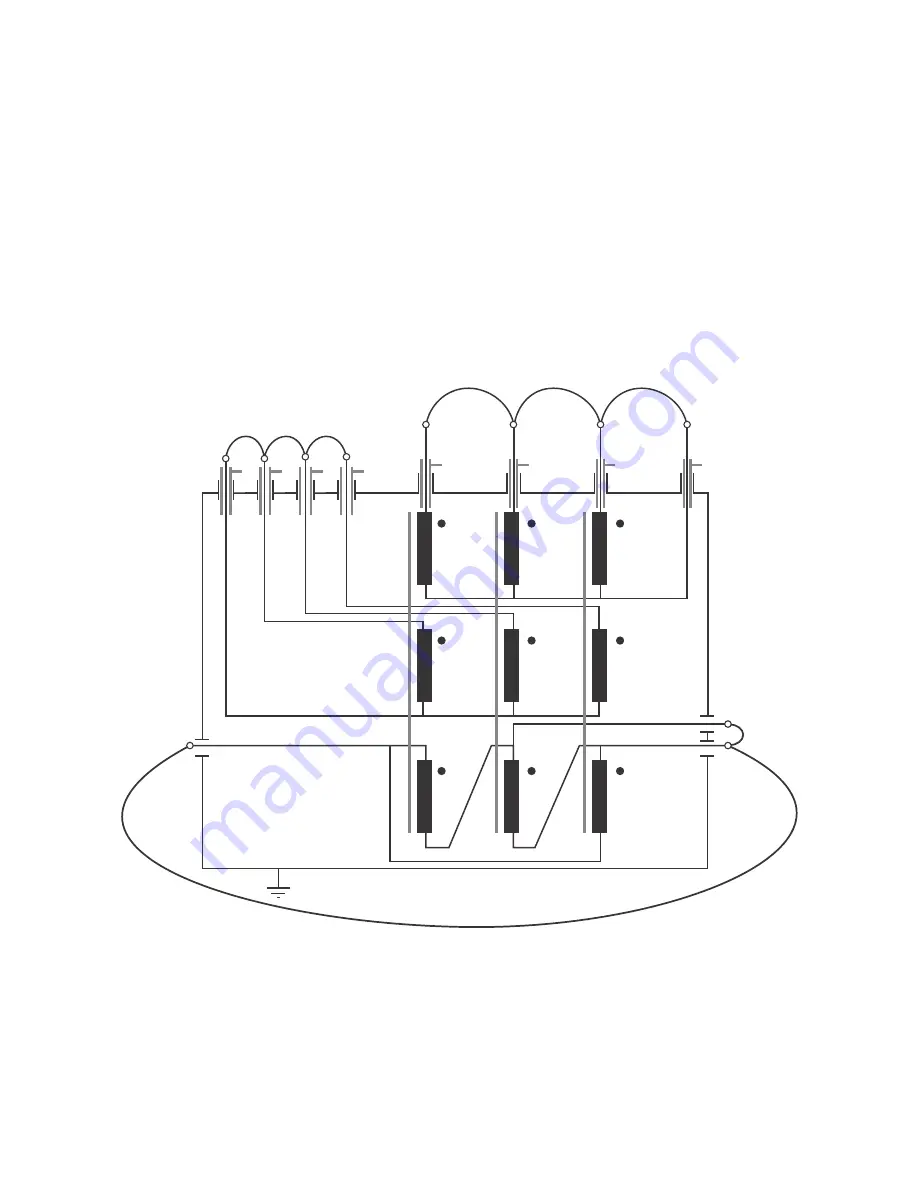
• All bushing terminals of one winding group, which means A, B, C (and Neutral) of high-voltage 

winding, A, B, C (and Neutral) of low-voltage winding and A, B, C (and Neutral) of tertiary winding 
have to be connected by a copper wire (see Figure 5-1).

Figure 5-1: Three-winding transformer with connected windings

• The neutral terminals of all Y-connected windings with outside-connected Neutral have to be 

disconnected from ground (tank).

• If the transformer has a tap changer then it should be set to the neutral position (0 or middle tap).
• Connect the 

Control Device

 + 

CP TD1

 ground terminal to the transformer's (substation) ground.

N (L)

C (L)

A (L)

B (L)

A (H)

B (H)

C (H)

N (H)

HV

LV

TV

B (T)

C (T)

A (T)

A

B

C

Summary of Contents for CP TD1

Page 1: ...CP TD1 User Manual...

Page 2: ...a embodied in this manual represent the technical status at the time of writing and are subject to change without prior notice We have done our best to ensure that the information given in this manual...

Page 3: ...nents of the CPC 80 17 2 5 1 CPC 80 front panel 17 2 5 2 CPC 80 mains power supply and Booster output 18 2 5 3 CPC 80 ePC Interfaces 19 2 6 TESTRANO 600 and CP TD1 equipment trolley 20 2 7 Functional...

Page 4: ...ctors 56 6 High voltage bushings 57 6 1 Introduction 57 6 2 Types of bushings 57 6 2 1 Condenser 57 6 2 2 Composite 58 6 2 3 Compound filled 58 6 2 4 Dry or unfilled 58 6 2 5 Oil filled 58 6 2 6 Oil i...

Page 5: ...read this manual before operating the CP TD1 and observe the safety installation and operation instructions therein Reading the CP TD1 User Manual alone does not release you from the duty to comply wi...

Page 6: ...NO 600 User Manual Contains information on how to use the TESTRANO 600 test system and relevant safety instructions CPC 100 PTM User Manual Contains information on how to use the Primary Test Manager...

Page 7: ...ection and Operation of Electrical Test Equipment EN 50110 1 VDE 0105 Part 100 Operation of Electrical Installations IEEE 510 IEEE Recommended Practices for Safety in High Voltage and High Power Testi...

Page 8: ...ned by OMICRON are authorized to operate the CP TD1 Before starting the work clearly establish the responsibilities Personnel receiving training instructions directions or education on the CP TD1 must...

Page 9: ...ou notice a rough running of the screw cap clean the screw thread and use a lubricant Vaseline recommended At the test object insert the high voltage cables plugs carefully until you feel a click posi...

Page 10: ...Manual is also considered part of being in accordance with the regulations Opening CP TD1 or its accessories invalidates all warranty claims 1 6 Static charges Static charges on bushings or other appa...

Page 11: ...ser will be required to correct the interference at his own expense Changes or modifications not expressly approved by the party responsible for compliance could void the user s authority to operate t...

Page 12: ...test procedures reduce the testing time to a minimum Test reports are generated automatically When used with the CPC 100 or CPC 80 the CP TD1 comes with its own CPC test card named TanDelta Tangent D...

Page 13: ...100 CPC 100 CP TD1 and the equipment trolley connected to the trolley s grounding bar and led to earth Grounding cable min 6mm CP TD1 Grounding terminal Data cable CPC 100 CP TD1 short type Via this d...

Page 14: ...d Soft touch keyboard Built in ePC Built in ePC with front panel control We recommend not to use more than 15 test cards or 50 test results in one test procedure see Note below I 0 Warning lights that...

Page 15: ...nnected to mains regardless whether or not an external booster is selected on the software tab Options Device Setup the green warning light 0 is on the outputs are turned off or the Emergency Stop but...

Page 16: ...ty interfaces are identical with the CPC 100 V0 version see above The network interface is an auto crossover Ethernet connector that can be connected to a network hub or directly to a PC or a notebook...

Page 17: ...on elements Test Start Stop Built in ePC Built in ePC with front panel control We recommend not to use 50 test results in one test procedure see Note below I 0 Warning lights that indicate either a sa...

Page 18: ...C 80 mains power supply and Booster output Figure 2 5 Mains power supply booster output and grounding terminal Mains power switch Mains power supply Ext Booster for example to power the CP TD1 Groundi...

Page 19: ...is properly connected to a PC or network Yellow LED lights if data is transferred from or to the network Red LED serves for diagnosis purposes The connector for external safety functions allows connec...

Page 20: ...software controls the CP TD1 CP TD1 s measuring inputs IN A and IN B connected to the cable drum for the measuring cables Equipment trolley Booster cable TESTRANO 600 CP TD1 Via this cable TESTRANO 6...

Page 21: ...panel Figure 2 7 TESTRANO 600 front panel with display USB Port for USB stick Red warning light Indicates possibly hazardous voltage and or current levels on the CP TD1 outputs Green light Safe opera...

Page 22: ...rrent 30 mA Warning light 2 steady on orange voltage 42 V LOW VOLTAGE terminal secondary side HIGH VOLTAGE terminal primary side EtherCAT RJ 45 socket for connecting an external EtherCAT slave to TEST...

Page 23: ...2 9 2 CP TD1 serial interface connector and measuring inputs Figure 2 10 Serial interface and measuring inputs of the CP TD1 right side of the device 2 9 3 CP TD1 high voltage connector Figure 2 11 H...

Page 24: ...Cleaning To clean one of the devices described in this document use a cloth dampened with isopropanol alcohol or water WARNING Death or severe injury caused by high voltage or current possible Prior...

Page 25: ...voltage by other persons and circumstances Verify a safe isolation of the test object Earth connect and shorten out the test object s terminals using a grounding set Protect yourself and your working...

Page 26: ...Never use the CP TD1 without a solid connection to ground with at least 6 mm Use a ground point as close as possible to the test object Make sure to position the test object or CP CAL in the high volt...

Page 27: ...t object to the CP TD1 s measuring inputs IN A and IN B 7 Connect the high voltage cable from the test object to the CP TD1 s high voltage output At the CP TD1 press the high voltage cable s plug to t...

Page 28: ...is double shielded and therefore safe However the last 50 cm 20 inch of this cable have no shield During a test consider this cable a life wire and due to the high voltage life hazardous WARNING Deat...

Page 29: ...aused by high voltage or current possible If the Ground check is disabled the operator is fully responsible for any hazard that might occur due to improper grounding Only deactivate the Ground check i...

Page 30: ...o lock vertical and remove the key to avoid anybody accidentally turning on the high voltage 4 Earth connect and shorten out the test object s terminals using a grounding set 5 Plug off the high volta...

Page 31: ...ory In an ideal capacitor without any dielectric losses the insulation current is exactly 90 leading according to the applied voltage For a real insulation with dielectric losses this angle is less th...

Page 32: ...tan and the vector diagram The correlation between the Dissipation Factor and Power Factor PF cos and the vector diagram are shown in Figure 4 3 Figure 4 3 Correlation between DF and PF jIm ICp I IRp...

Page 33: ...of the time but at times change their position through tunneling or thermal activation 2 Space Charge Polarization If different dielectrics with different permittivities and conductivities are presen...

Page 34: ...rature With higher temperatures the viscosity of the oil decreases so the particles ions and electrons can move easier and faster Thus the DF increases with temperature Figure 4 6 DF of new and aged o...

Page 35: ...figures show the frequency dependency for transformer windings oil paper insulation and an OIP bushing See Figures 4 8 and 4 9 T Figure 4 8 Frequency dependent dissipation factor of a power transform...

Page 36: ...or contact problems Figure 4 10 shows a measurement of a 6kV motor Above 4kV partial discharges occur which increase the dissipation factor Figure 4 10 Voltage dependent dissipation factor of a 6 kV m...

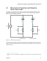
Page 37: ...test object with losses C2 the loss free reference capacitor Figure 4 11 CP TD1 measuring principle The CP TD1 test system utilizes a method similar to that of the Schering bridge The main difference...

Page 38: ...on configuration the currents via IN A and IN B are measured or not see Table 4 1 below The measurement result is the sum of all measured channels In the GST configuration 4 configurations are possib...

Page 39: ...ge winding A B C and Neutral of low voltage winding and A B C and Neutral of tertiary winding have to be connected by a copper wire see Figure 5 1 Figure 5 1 Three winding transformer with connected w...

Page 40: ...y the correction has limited accuracy Testing at very low temperatures provides less accurate results and should be avoided if possible Other factors like relative humidity and the general weather con...

Page 41: ...low voltage winding and ground Figure 5 2 Insulations of a two winding transformer In case of core type transformers insulation CHL is made of barriers and spacers which give it mechanical stability...

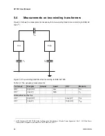
Page 42: ...P TD1 are connected Figure 5 3 CP TD1 connected to a two winding transformer for the measurement of CHL and CH With this setup 3 configurations are available see Table 5 1 below CHL and CH can be meas...

Page 43: ...for the measurement of CHL and CL With this setup 3 configurations are available as well see Table 5 2 below As CHL has been measured before usually only CL is measured in this second measurement Tabl...

Page 44: ...test according to IEEE 62 1995 1 ANSI Standard 62 1995 IEEE Guide for Diagnostic Field testing of Electric Power Apparatus Part 1 Oil Filled Power Transformers Regulators and Reactors IEEE New York 19...

Page 45: ...in MS Excel format Figure 5 6 Two winding transformer test preparation with CPC Editor Figure 5 7 10 kV results for a two winding transformer 50 Hz 5 4 2 Measurements on a two winding transformer with...

Page 46: ...k and insulation CHT between the high voltage winding and the tertiary windings CT is similar to CL in a two winding transformer whereas CL in a three winding transformer is mainly formed by the insul...

Page 47: ...preferred to assess each part of the insulation individually they are less commonly used Table 5 4 Modes available with a measurement setup as seen in Figure 5 9 Mode IN A IN B Ground Result UST A Mea...

Page 48: ...5 6 below Figure 5 10 CP TD1 connected to a three winding transformer for the measurement of CH With this setup the following 3 configurations are available Table 5 6 Modes available with a measureme...

Page 49: ...5 6 below Figure 5 11 CP TD1 connected to a three winding transformer for the measurement of CT With this setup the following 3 configurations are available Table 5 7 Modes available with a measureme...

Page 50: ...95 IEEE Guide for Diagnostic Field testing of Electric Power Apparatus Part 1 Oil Filled Power Transformers Regulators and Reactors IEEE New York 1995 Table 5 8 The six necessary measurements Test mod...

Page 51: ...inding transformer measurement with the CPC Editor Due to the high amount of measuring data the test is split into three single test files The first file contains the tests with the high voltage windi...

Page 52: ...CP TD1 User Manual 52 OMICRON Figure 5 15 Measurement of CH and CHL in GST g B mode Figure 5 16 Voltage scan of high voltage windings to tank and core GST gA B...

Page 53: ...or HL are prepared analog to the examples Second file A second test file contains the tests with the low voltage winding connected to the high voltage output of the CP TD1 Figure 5 18 shows the first...

Page 54: ...winding Figure 5 19 Connection instructions for the tests with energized tertiary winding The prepared tests are to be uploaded to the CPC 100 as xml files without results After the test is done this...

Page 55: ...eparing the test in the office by utilizing the CPC Editor the testing time on site can be reduced to a minimum Figure 5 21 Voltage scan for H L V 50 Hz 1 H HL In line 4 the difference of the capacity...

Page 56: ...ng with a tap for the low voltage output Only one measurement is made of the winding to tank and core All high voltage and low voltage terminals are connected together as they are building the high vo...

Page 57: ...forms including 6 2 1 Condenser This type is most frequently used for high voltage bushings and it is therefore the main one focused in this guide Cylindrical conducting layers are arranged coaxially...

Page 58: ...illed A bushing consisting of a porcelain tube with no filler in the space between the shell and the conductor These are usually rated 25 kilovolts and below 6 2 5 Oil filled A bushing where the space...

Page 59: ...erature significantly affect dissipation factor readings on certain types of bushings For comparative purposes readings should be taken at the same temperature Corrections should be applied before com...

Page 60: ...less Routine tap insulation tests are not normally recommended for bushings that are rated 69 kilovolts and below with dissipation factor taps However a dissipation factor test of the tap insulation s...

Page 61: ...he upper porcelain rain shed and the current carrying or center conductor The test is performed by energizing one or more electrodes placed around the bushing porcelain with the bushing center conduct...

Page 62: ...gh in this case the equipment should be retested at a higher temperature Bushings should not be tested when their temperatures are much below freezing because moisture may have changed to ice which ha...

Page 63: ...the surface current This connection technique is also very useful when the insulation of cables is measured When transformer bushings are tested IN A and IN B can be used to measure two bushings at a...

Page 64: ...utput 0 12 kV AC 15 400 Hz 2 300 mA 3600 VA 2 min 100 mA 1200 VA 60 min Table 7 2 Test frequencies Range Typical accuracy 15 400 Hz error 0 005 of reading 50 Hz 60 Hz Measurement mode suppressing the...

Page 65: ...V error 0 2 of reading Ix 8 mA Utest 300 V 10 kV Table 7 7 Dissipation factor DF Range Typical accuracy Conditions 0 10 capacitive error 0 1 of reading 0 005 1 1 Reduced accuracy of DF at mains freque...

Page 66: ...edance Z Range Typical accuracy Conditions 1 k 1200 M error 0 5 of reading Vtest 300 V 10 kV Table 7 11 Inductance Lx Range Typical accuracy 1 H 1000 kH error 0 3 of reading Table 7 12 Quality factor...

Page 67: ...2 x 14 6 inches CP TD1 CPC 100 equipment trolley Equipment 85 kg 187 5 lb 750 x 1050 x 600 mm 29 5 x 41 3 x 23 6 inches Equipment packing 125 kg 275 8 lb CP TD1 TESTRANO 600 equipment trolley Equipme...

Page 68: ...IEC EN 61326 1 industrial electromagnetic environment FCC subpart B of part 15 class A Other Shock IEC 60068 2 27 operating 15 g 11 ms half sinusoid Vibration IEC 60068 2 6 operating 10 150 Hz accele...

Page 69: ...43 59495 4444 Additionally you can find our Service Center or Sales Partner closest to you at www omicronenergy com Customer area stay informed www omicronenergy com customer The customer area on our...

Page 70: ...ENU 1035 05 03...

Reviews: