Transformer
6 - 5
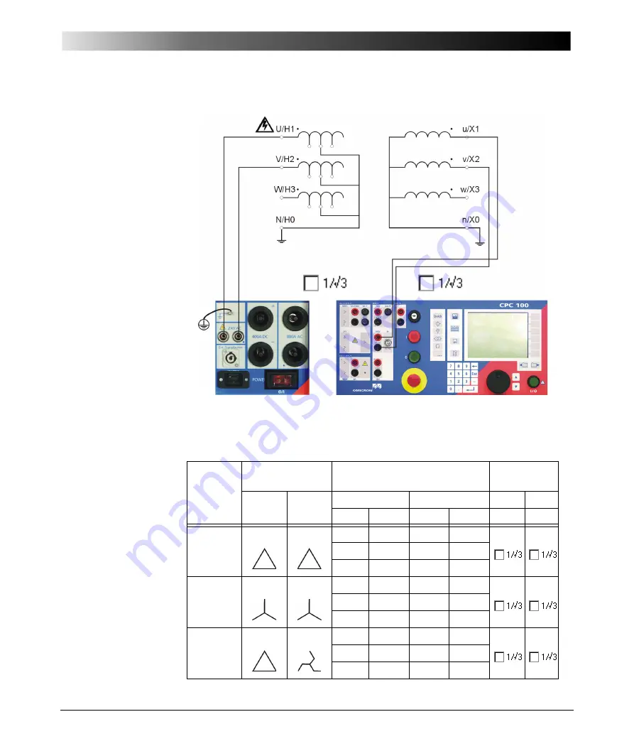
Figure 4:
Setup for a power
transformer ratio tap
changer test
Table 1 shows the Vprim and Vsec settings on the
TRRatio
test card for different
connections of the transformer under test.
Table 1:
TRRatio
test card
settings for different
transformer’s windings
connections
IEC 60076
vector
group
Winding
Connection to
CPC 100
TRRatio
settings
HV/H
LV/X
2 kV
output
V1 AC
input
red
black
red
black
Vprim Vsec
Dd0
U/H1
V/H2
u/X1
v/X2
V/H2
W/H3
v/X2
w/X3
W/H3 U/H1
w/X3
u/X1
Yy0
U/H1
V/H2
u/X1
v/X2
V/H2
W/H3
v/X2
w/X3
W/H3 U/H1
w/X3
u/X1
Dz0
U/H1
V/H2
u/X1
v/X2
V/H2
W/H3
v/X2
w/X3
W/H3 U/H1
w/X3
u/X1
U
W
V
u
w
v
U
W
V
u
w
v
U
V
W u
v
w
Summary of Contents for CPC 100
Page 12: ...CPC 100 V1 41 x...
Page 28: ...CPC 100 V1 41 1 16...
Page 90: ...CPC 100 V1 41 3 14...
Page 194: ...CPC 100 V1 41 6 30...
Page 250: ...CPC 100 V1 41 8 32 Figure 24 Settings of Amplifier test card for this example use case...
Page 258: ...CPC 100 V1 41 9 4...
Page 264: ...CPC 100 V1 41 10 6...
Page 282: ...CPC 100 V1 41 12 10 Figure 9 Saving tests with the CPC Editor...
Page 284: ...CPC 100 V1 41 12 12...
Page 312: ...CPC 100 V1 41 14 12...
Page 316: ...CPC 100 V1 41 15 4...
Page 350: ...CPC 100 V1 41 16 34...
Page 372: ...OMICRON Contact Addresses 22...


