CPC 100 V1.41
8 - 12
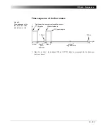
Figure 7:
Sequencer
test card
with parameters and
measurements of the
four states
1
Current values < 50A do not initiate an "Overload" when the current circuit opens. For this
reason, a nominal current value of 50A was chosen here, even though the CB is open.
Note:
For debouncing purposes, at CB closing time measurements,
CPC 100
adds a fixed time of 100ms to the measured value. In order
to determine the true CB closing time value, these 100ms need to be
deducted from the value displayed in the measurement table.
State 2: "wait for the CB to close"
Short dead time. Set to output 50A
until the "Overload" trigger condition
that started state 2 clears.
The measurement table shows for
state 2 that the short dead time + the
CB closing time lasted 477ms. This
time also includes the additional
time to compensate for the
debounce (see note below).
The actual value for CB close equals
477ms - 100ms =
377ms
.
Note that the r.m.s. measurement of
IOut reacts slow and therefore the
measurement table does not show
the full current.
State 3: "wait for the CB to open"
Like state 1.
State 1: "wait for the CB to open"
Set to output 400A until the trigger
condition "Overload" occurs.
Here, trigger condition "Overload"
means:
CPC 100
cannot provide the
400A any longer because of the
opening CB contact. Therefore, the
opening CB contact terminates
state 1.
The measurement table shows for
state 1 that the relay time + the CB
opening time lasted 290ms.
State 4: "wait for the CB to close"
Long dead time. Set to output 50A
1
until the "Overload"
trigger condition that started state 4 clears.
The measurement table shows for state 4 that the long
dead time + the CB closing time lasted 3.1910s. This
time also includes the additional time to compensate
for the debounce (see note below).
The actual value for CB close equals
3.1910s - 100ms =
3.0910s
.
Not relevant for this test.
Summary of Contents for CPC 100
Page 12: ...CPC 100 V1 41 x...
Page 28: ...CPC 100 V1 41 1 16...
Page 90: ...CPC 100 V1 41 3 14...
Page 194: ...CPC 100 V1 41 6 30...
Page 250: ...CPC 100 V1 41 8 32 Figure 24 Settings of Amplifier test card for this example use case...
Page 258: ...CPC 100 V1 41 9 4...
Page 264: ...CPC 100 V1 41 10 6...
Page 282: ...CPC 100 V1 41 12 10 Figure 9 Saving tests with the CPC Editor...
Page 284: ...CPC 100 V1 41 12 12...
Page 312: ...CPC 100 V1 41 14 12...
Page 316: ...CPC 100 V1 41 15 4...
Page 350: ...CPC 100 V1 41 16 34...
Page 372: ...OMICRON Contact Addresses 22...


