Version April 2019
8
EN
HST – S – 315 2.0 User’s Manual
O . M . I . S . A . S r l
Via Verga 9/11
20845 Sovico (MB), Italy
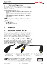
terminal (connector type A0P), the screen displays
A0P
. Con-
necting the adapter with one blue terminal (connector type
A01) will make the display switch to
A01
. The adapter with
one red terminal (connector type A02), when used, will result
in
A02
being displayed. The adapter with one white terminal
(connector type A04) matches
A04
on the display screen.
As soon as a welding adapter was plugged into the welding
cable of the unit,
all
indicators of the cable/adapter type
(display screen, color of terminal, identifier printed on ter-
minal) must match the fitting (size and manufacturer) that
is going to be used.
Failure to comply with this instruction will result in a poor
welding outcome, may cause damage to the welding unit,
and will cancel any and all warranties under which the unit
is. Bear in mind the following matches:
Connector type A00 – yellow terminal
—— Fitting sized
32 - 160 mm, of the makes Valsir, Akatherm, Eurofusion,
Geberit, Waviduo, Coes
Connector type A0P – green terminal
—— Fitting sized
200 - 315 mm, of the make Waviduo
Connector type A01 – blue terminal
—— Fitting sized
200 - 315 mm, makes Valsir, Akatherm, Eurofusion, Wavisolo
C o n n e c t o r t y p e A 0 2 – re d t e r m i n a l
— — F i t t i n g s i z e d
200 - 315 mm, of the make Geberit
Connector type A04 – white terminal
—— Fitting sized
200 - 315 mm, of the make Coes
Connect the connection terminals to the fitting and check for proper
fit. The contact surfaces of the connection terminals and the fitting
have to be clean. Dirty terminals may lead to improper welding and
also to overheated and fused terminal plugs.
Important
When using the so-called multi-adapter for the simultaneous
welding with two fittings, make sure to connect it properly,
as described in Sect. 5.8.
After the welding cable was connected to the welding unit, the dis-
play screen shows the connection type, A00, A01, etc. As soon as the
welding cable is plugged into the electrofusion fitting to be processed,
the yellow LED (Fitting connected) lights up. For the connection type
A04 (white connector), additionally the diameter of the connected
Coes fitting is displayed: 200 mm, 250 mm or 315 mm.
After connecting the electrofusion fitting, start the welding process by
pressing the START key. Pressing this key will cause the welding unit
to show the welding time, which is then counted down.
Depending on the processed fitting, the welding time, which is counted
down on the display, may be up to 700 s.
5.3 Welding Process
The welding process is monitored for its entire duration, applying the
welding parameters computed for the electrofusion fitting.
5.4 End of Welding
The welding process was completed successfully if the actual weld-
ing time is 0 s (
000
on the display screen), the green LED (End) lights
up at that point, and the audible signal beeps twice. As opposed to

