OMNI 4000/7000 Operations and Maintenance Guide
– Rev F
7-6
Maintenance
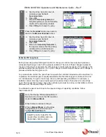
13.
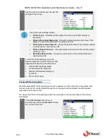
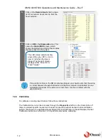
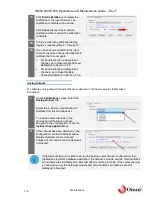
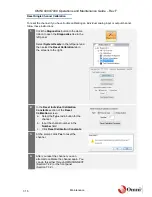
Click
End Calibration
to complete the
calibration of the input channel. The
calibration constants will be saved.
Click
Cancel
at any time to end the
calibration without saving the calibration
constants.
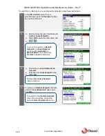
14.
Continue calibrating additional analog
inputs by repeating Steps 1 through 13.
15.
If you have trouble calibrating the input
channel, reset the channel and attempt to
calibrate the channel again.
•
For troubleshooting a single input
channel, go to Reset Single Channel
Calibration in Section 7.2.5.
•
For troubleshooting multiple input
channels, go to Reset Multiple
Channel Calibration in Section 7.2.5.
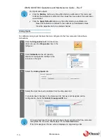
Analog Outputs
To calibrate analog output channels that are configured in the flow computer, follow these
instructions:
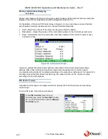
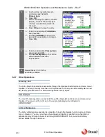
1.
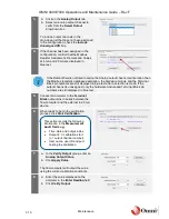
On the
Calibrations
screen, select the
Analog Outputs
tab.
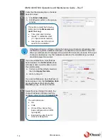
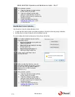
Select the 4
‒20 mA output channel to
calibrate from the drop-down list.
To include output channels in the
drop-down list that have not been
assigned in the configuration, check the
Include Unassigned I/O
box.
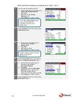
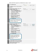
2.
If the channel has been assigned in the
configuration, confirm that the Modbus
Register Assignment, Remark and
Values at 4 mA and 20 mA are displayed
in blue text.
If the Remarks field is not filled in during the Analog output channel configuration, then
the Modbus register’s database description, the hardware module and the Terminal Block
pin numbers are still displayed in blue text after a selection is made. If the output channel
is unassigned, only the hardware module and Terminal Block pin numbers are still
displayed in blue text.

