background image

support@omnicomm-world.com   |   Installation manual Omnicomm 2.0 terminals v2.2

7

.16   |   61

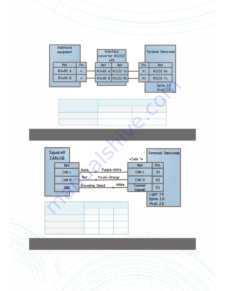
FIGURE 86. DIAGRAM OF CONNECTING ADDITIONAL EQUIPMENT TO RS232 INTERFACES 

OF OMNICOMM PROFI 2.0 AND OPTIM 2.0 TERMINALS VIA RS232/485 CONVERTER

FIGURE 87. DIAGRAM OF CONNECTING OMNICOMM 2.0 TERMINALS TO CAN BUS 

USING CAN READER MANUFACTURED BY SQUARELL COMPANY

Terminal Model

Contact No.

X 1

X 2

Omnicomm Optim 2.0

8 or 9 (“SIDE 1”)

19 or 20 (“SIDE 1”)

Omnicomm Pro

fi

 2.0

2 (“SIDE 2”)

7 (“SIDE 2”)

Terminal Model

Contact No.

X 1

X 2

X 3

Omnicomm Light 2.0

6

12

1

Omnicomm Optim 2.0

11

22

1 or 2

Omnicomm Pro

fi

 2.0

8

18

2 or 12

Summary of Contents for Light 2.0

Page 1: ...Omnicomm Terminals Profi 2 0 Profi 2 0 WiFi Optim 2 0 Light 2 0 7 495 108 0423 68 70 build 1 Butirskiy Val Moscow Russia 127055 WWW OMNICOMM WORLD COM Installation manual Version 2 27 16...

Page 2: ...peed sensor to Omnicomm Profi 2 0 AND Profi 2 0 WiFi Terminals 9 4 3 Connecting TACHOMETER TO OMNICOMM Profi 2 0 Profi 2 0 WiFi and Optim 2 0 Terminals 10 4 4 Connection of fuel level sensors 10 4 4 1...

Page 3: ...Profi 2 0 and Profi 2 0 WiFi Terminal 17 4 20 1 Connection of cables to the connectors of Omnicomm Profi 2 0 and Profi 2 0 WiFi Terminals using goffers 17 4 20 2 Connecting cables to the connectors of...

Page 4: ...ht 2 0 Terminal 28 7 4 Issuance of the installation certificate 28 APPENDIX A General and mounting dimensions of the Omnicomm 2 0 Terminals 29 APPENDIX B Connector pin assignments for the Omnicomm 2 0...

Page 5: ...in the GSM network and with external networks including the Internet Home network the territory within which it is possible to use the services of an operator without resorting to roaming services Ro...

Page 6: ...urrent valid certificate confirming the required training with the Omnicomm company During commissioning works it is obligatory to comply with the safety requirements specified in the operating docume...

Page 7: ...rooves of the connector and install the SIM card in it with the contact surface facing up Figure 4 4 Install the SIM card holder into the connector grooves Figure 5 FIGURE 5 3 3 INSTALLING A SECOND SI...

Page 8: ...for a vehicle not equipped with a ground switch Vehicles equipped with ground switch are connected the same way 4 1 1 Connection to the power circuit of the vehicles not equipped with a ground switch...

Page 9: ...BR 15 galvanic isolator in accordance with Figures 65 and 68 For two LS 20230 fuel level sensors and BIS 20240 spark protection unit connection to Omnicomm Profi 2 0 Terminal must be performed via BR...

Page 10: ...ction to tachometer is shown in Figure 81 4 4 CONNECTION OF FUEL LEVEL SENSORS 4 4 1 Connecting LLS fuel level sensor to Omnicomm Profi 2 0 AND Profi 2 0 WiFi Terminal Omnicomm Profi 2 0 Terminal supp...

Page 11: ...sensor is conducted in accordance with Figure 73 4 5 CONNECTION OF THE PANIC BUTTON Connection of panic button proceeds according to the colours of the wires and the diagram for Omnicomm Profi 2 0 Omn...

Page 12: ...gure 9 FIGURE 9 It is possible to use EXSNET magnetic cards of X series with one wire and em Marine magnetic cards in place of the iButton reader 4 9 CONNECTION OF AN ACOUSTIC RADIATOR TO THE OMNICOMM...

Page 13: ...voltage value corresponding to the maximum value of the measured quantity then press Save Settings Check the display of the current values of the input voltage and the measured value in the settings...

Page 14: ...devices as optional equipment To control additional equipment when connecting to a universal input it is recommended that you use the available signals for example from the control elements or instal...

Page 15: ...ted in accordance with Figure 77 Current consumption of additional equipment must be no more than 300 mA Omnicomm 2 0 Terminals excluding Smart 2 0 provide for up to three operation rules for every co...

Page 16: ...ing is 1 sec Possible values from 1 to 10 To add a geofence press the button Import and select the xml file with geofence settings Maximum number of geofences is 6 Maximum number of angular points is...

Page 17: ...ble must not be placed near any moving parts of the vehicle 4 20 CONNECT THE CABLES TO THE CONNECTORS OF THE OMNICOMM PROFI 2 0 AND PROFI 2 0 WIFI TERMINAL Connection of the cables to the connectors o...

Page 18: ...the cable wires that are attached to SIDE 2 connectors into the rubber cable input Place at first the GSM antenna cable into another rubber cable input and then 10 wires of the cable attached to SIDE...

Page 19: ...nectors Figure 15 FIGURE 15 5 REQUIRED OPERATIONAL SETTINGS FOR OMNICOMM 2 0 TERMINALS 5 1 TERMINAL CONFIGURATION USING OMNICOMM CONFIGURATOR Connect the PC to the OmnicommTerminal in accordance With...

Page 20: ...TERMINAL FIGURE 17 INSTALLATION DIMENSIONS OF THE OMNICOMM OPTIM 2 0 AND OMNICOMM LIGHT 2 0 TERMINALS 5 Install the Omnicomm Terminal in the appropriate place of installation 6 Secure Omnicomm Termina...

Page 21: ...faced adhesive tape when mounting the antenna in place Apply a uniform layer of glue to the base of the antenna 4 Attach the antenna base to the area of installation 5 Allow adequate time for the hard...

Page 22: ...the double faced adhesive tape on the surface of the WiFi antenna Attach the adhesive side of the WiFi antenna to the installation site Allow for the necessary time for the hardening of glue around th...

Page 23: ...itchadapter Figure23 FIGURE 20 FIGURE 21 FIGURE 22 FIGURE 23 6 8 INSTALLATION OF THE IBUTTON READER FOR THE OMNICOMM PROFI 2 0 AND OMNICOMM PROFI 2 0 WIFI TERMINAL The iButton reader must be installed...

Page 24: ...el in the cabin of the vehicle Installation of acoustic radiator should depend on the installation location and method of attachment 6 9 1 Attaching acoustic radiator with screws self driving screws o...

Page 25: ...ed Dismantle acoustic radiator racks by unscrewing the screws Apply an even layer of glue on the acoustic radiator board and attach it to the surface of the installation site Figure 29 FIGURE 29 Secur...

Page 26: ...alled washers in advance FIGURE 32 7 DELIVERY OF ASSEMBLED AND ADJUSTED PRODUCT 7 1 Sealing of Omnicomm Profi 2 0 and Profi 2 0 WiFi Terminal 7 1 1 Installing OF PROTECTIVE cover for Omnicomm Profi 2...

Page 27: ...re through the holes of the casing of Omnicomm Profi 2 0 or Profi 2 0 WiFi Terminal and protective cover Figure 35 FIGURE 35 2 Insert the ends of the wire through the rotary seal holes 3 Tighten the w...

Page 28: ...be downloaded from the company website of Omnicomm at www omnicomm online com The Certificate of Installation must include the name of the organisation for which the product was installed the name of...

Page 29: ...inals v2 27 16 29 APPENDIX A General and mounting dimensions of the Omnicomm 2 0 Terminals FIGURE 39 DIMENSIONAL DRAWING OF THE OMNICOMM PROFI 2 0 AND PROFI 2 0 WIFI TERMINALS FIGURE 40 DIMENSIONAL DR...

Page 30: ...CTOR PINS OF SIDE 2 OF THE OMNICOMM PROFI 2 0 AND PROFI 2 0 WIFI TERMINAL SIDE 1 connector No of contact Signal name Designation Colour of wire in the cable 1 On board supply voltage Power supply Red...

Page 31: ...icrophone Green red SIDE 2 connector No of contact Signal name Designation Colour of wire in the cable 1 iButton iButton Pink blue 2 Line RS 232 Rx Rx RS 232 Pink 3 Universal input 4 Input 4 Black yel...

Page 32: ...nk 9 Line RS 232 RX No 2 RS 232 No 2 RX Pink and Brown 10 Line B RS 485 LLS B RS 485 LLS Blue white 11 CAN L CAN L Purple white 12 On board supply voltage Power supply Red 13 Ignition key IGN Yellow 1...

Page 33: ...of wire in the cable 1 Ground minus for power Ground White 2 Not used NC 3 Universal input 2 Input 2 Black and white 4 Not used NC 5 Line B RS 485 B RS 485 Blue white 6 Line CAN L CAN L Purple white 7...

Page 34: ...pcs 3 Glue or double sided adhesive tape When installing acoustic radiator with glue 4 Wire stripper 5 Pliers or tool for crimping sleeves 6 Industrial dryer or miniature burner Shrink sleeve insulati...

Page 35: ...omm Terminal and is converted into a physical quantity measured by sensor Conversion is performed according to a linear law given by two points when configuring the Omnicomm Terminal FIGURE 48 ASSIGNI...

Page 36: ...if the Terminal input receives a voltage signal that is greater than the voltage activation threshold and for more than 1000 s Activation of potential input logical unit is transmitted to Omnicomm On...

Page 37: ...rt omnicomm world com Installation manual Omnicomm 2 0 terminals v2 27 16 37 FIGURE 50 DIFFERENT OUTPUT VALUES OF IMPULSE AND POTENTIAL TYPES OF INPUTS WHEN PROCESSING THE SIGNAL OF THE DOOR OPENING S...

Page 38: ...connection method recommended for LLS AF Analog Voltage or current signal value of which is proportional or inversely proportional to the measured value Temperature pressure humidity etc Sensors of te...

Page 39: ...when brought into the metal zone Available with up to 30 mm working range More protected from false positives but do not work with non metallic objects With hall effect or reed relay are triggered wh...

Page 40: ...minimum value V 0 8 Maximum value of the measured value 125 Pressure corresponding to the maximum value V 14 0 Note if the maximum or minimum values of measurement sensor are unknown you are allowed...

Page 41: ...heenginethatdrivestheworkingbodyofadditionalattachmentsand processes data in Omnicomm Online calculate work time downtime etc For example for the purpose of control it was not possible to locate the s...

Page 42: ...YES Inversion of potential signal NO Explanation With closed contact of the sensor voltage close to 0 V ground voltage occurs at the input of the Omnicomm Terminal When contact is broken voltage with...

Page 43: ...meters must be preset in Omnicomm Configurator Parameter Value Input type Potential Voltage threshold for actuation V 3 3 Pull up resistor NO Inversion of potential signal NO Explanation The threshold...

Page 44: ...G Connection diagrams for Omnicomm Profi 2 0 Profi 2 0 WiFi Optim 2 0 and Light 2 0 FIGURE 53 DIAGRAM OF CONNECTION TO POWER SUPPLY CIRCUIT OF THE VEHICLE NOT EQUIPPED WITH GROUND SWITCH FIGURE 54 DI...

Page 45: ...0 terminals v2 27 16 45 FIGURE 55 DIAGRAM OF CONNECTION TO POWER SUPPLY CIRCUIT OF THE VEHICLE NOT EQUIPPED WITH GROUND SWITCH FIGURE 56 DIAGRAM OF CONNECTION TO POWER SUPPLY CIRCUIT OF THE VEHICLE A...

Page 46: ...llation manual Omnicomm 2 0 terminals v2 27 16 46 FIGURE 57 DIAGRAM OF CONNECTION TO POWER SUPPLY CIRCUIT OF THE VEHICLE AFTER GROUND SWITCH FIGURE 58 DIAGRAM OF CONNECTION TO POWER SUPPLY CIRCUIT OF...

Page 47: ...27 16 47 FIGURE 59 DIAGRAM OF CONNECTION TO POWER SUPPLY CIRCUIT OF THE VEHICLE BEFORE GROUND SWITCH WITH LLS 30160 20160 FUEL LEVEL SENSOR FIGURE 60 DIAGRAM OF CONNECTION TO POWER SUPPLY CIRCUIT OF...

Page 48: ...n manual Omnicomm 2 0 terminals v2 27 16 48 FIGURE 61 DIAGRAM OF CONNECTION TO POWER SUPPLY CIRCUIT OF THE VEHICLE BEFORE GROUND SWITCH FIGURE 62 DIAGRAM OF CONNECTION TO VEHICLE BATTERY WHEN IT IS NO...

Page 49: ...ual Omnicomm 2 0 terminals v2 27 16 49 FIGURE 63 DIAGRAM OF CONNECTION TO VEHICLE BATTERY WHEN IT IS NOT POSSIBLE TO CONNECT TO IGNITION KEY FIGURE 64 DIAGRAM OF CONNECTION TO VEHICLE BATTERY WHEN IT...

Page 50: ...omm world com Installation manual Omnicomm 2 0 terminals v2 27 16 50 FIGURE 65 DIAGRAM OF CONNECTING POWER SUPPLY LLS 20230 FUEL LEVEL SENSOR BIS 20240 SPARK PROTECTION UNIT AND SRD TO OMNICOMM PROFI...

Page 51: ...Installation manual Omnicomm 2 0 terminals v2 27 16 51 FIGURE 66 DIAGRAM OF CONNECTING POWER SUPPLY OF TWO LLS 20230 FUEL LEVEL SENSORS TO OMNICOMM PROFI 2 0 TERMINAL USING ONE SPARK PROTECTION UNIT...

Page 52: ...URE 67 DIAGRAM OF CONNECTING POWER SUPPLY AND TWO LLS 20230 FUEL LEVEL SENSORS TO OMNICOMM PROFI 2 0 TERMINAL USING TWO SPARK PROTECTION UNITS BIS 20240 FIGURE 68 DIAGRAM OF CONNECTING LLS 20230 FUEL...

Page 53: ...9 DIAGRAM OF CONNECTING OMNICOMM PROFI 2 0 TERMINAL TO FUEL LEVEL SENSOR LLS 20160 30160 FIGURE 70 DIAGRAM OF CONNECTING OMNICOMM LIGHT 2 0 OR OMNICOMM OPTIM 2 0 TERMINALS TO FUEL LEVEL SENSORS LLS 20...

Page 54: ...anual Omnicomm 2 0 terminals v2 27 16 54 FIGURE 71 DIAGRAM OF CONNECTING OMNICOMM PROFI 2 0 TERMINAL TO SEVERAL FUEL LEVEL SENSORS LLS 30160 20160 FIGURE 72 DIAGRAM OF CONNECTING LLS AF 20310 FUEL LEV...

Page 55: ...SENSOR OF OMNICOMM LIGHT 2 0 OR OMNICOMM OPTIM 2 0 TERMINALS FIGURE 74 PANIC BUTTON WIRING DIAGRAM Terminal Model Contact No X Omnicomm Light 2 0 3 or 9 Omnicomm Optim 2 0 4 5 15 or 16 Terminal Model...

Page 56: ...Installation manual Omnicomm 2 0 terminals v2 27 16 56 FIGURE 75 CONNECTING VOICE COMMUNICATION KIT TO OMNICOMM PROFI 2 0 TERMINAL FIGURE 76 WIRING FOR CONNECTING AN ACTIVE SPEAKER AND MICROPHONE TO O...

Page 57: ...lay with response voltage suitable for on board network voltage of the vehicle 12 V or 24 V FIGURE 78 DIAGRAM OF CONNECTING A TACHOGRAPH TO UNIVERSAL INPUT Terminal Model Contact No Wire colour X Omni...

Page 58: ...79 DIAGRAM OF CONNECTING TO TRANSIT SPEED SENSOR FIGURE 80 DIAGRAM OF CONNECTING TO IMPULSE SPEED SENSOR FIGURE 81 DIAGRAM OF CONNECTING OF OMNICOMM TERMINALS TO TACHOMETER OF OMNICOMM PROFI 2 0 AND O...

Page 59: ...RE 83 DIAGRAM OF CONNECTING OF STANDARD FUEL SENSOR OF THE VEHICLE WITH ANALOG OUTPUT TO OMNICOMM PROFI 2 0 OPTIM 2 0 TERMINAL VIA PAM SIGNAL CONVERTER Terminal Model Contact No X Omnicomm Optim 2 0 1...

Page 60: ...m Profi 2 0 6 SIDE 2 iButton 1 SIDE 2 FIGURE 84 DIAGRAM OF CONNECTING TEMPERATURE SENSORS DS18B20 TO 1 WIRE BUS FIGURE 85 DIAGRAM OF CONNECTING ADDITIONAL EQUIPMENT TO RS232 INTERFACES OF OMNICOMM PRO...

Page 61: ...MINALS VIA RS232 485 CONVERTER FIGURE 87 DIAGRAM OF CONNECTING OMNICOMM 2 0 TERMINALS TO CAN BUS USING CAN READER MANUFACTURED BY SQUARELL COMPANY Terminal Model Contact No X 1 X 2 Omnicomm Optim 2 0...

Page 62: ...D OPTIM 2 0 TERMINALS FIGURE 89 DIAGRAM OF CONNECTING ADDITIONAL EQUIPMENT TO EIA485 INTERFACE OF OMNICOMM PROFI 2 0 AND OPTIM 2 0 TERMINALS VIA RS232 485 CONVERTER Terminal Model Contact No X 1 X 2 O...

Page 63: ...FIGURE 91 CONNECTION DIAGRAM FOR THE OMNICOMM 2 0 TERMINALS TO THE PC Connector pins of OmnicommTerminals for all universal inputs and Figures 92 96 are specified in the table below Terminal Model Co...

Page 64: ...ING DT14V TEMPERATURE SENSOR TO UNIVERSAL INPUT FIGURE 93 DIAGRAM FOR CONNECTING ANALOG SENSOR WITH STANDARDISED VOLTAGE OUTPUT FOR SENSORS WHOSE 12 V 24 V VOLTAGE IS IN THE POWER SUPPLY RANGE TO UNIV...

Page 65: ...com Installation manual Omnicomm 2 0 terminals v2 27 16 65 FIGURE 95 DIAGRAM OF CONNECTING A CONTACT SENSOR TO UNIVERSAL INPUT FIGURE 96 DIAGRAM FOR CONNECTING AN OPEN COLLECTOR SENSOR WITH N P N OUT...

Page 66: ...bor and additionally equipped with connectors Signal removal devices SRD B 70 can be purchased directly from the manufacturer or previously installed SRD can be used It is however necessary to observe...

Page 67: ...ns equipped with fuel dispensing counters with impulse output To connect counter impulse output to the first universal input of Omnicomm Profi or Profi 2 0 Terminal Select Impulse operating mode and e...

Page 68: ...ation interval must be increased 6 Record the number of impulses counted by the Terminal during the fuel dispensing process which is displayed in the Current value at input field upon expiration of da...

Reviews: