80-J4866-2 Rev. G
MAY CONTAIN U.S. AND INTERNATIONAL EXPORT CONTROLLED INFORMATION
11-11
Vehicle Data Bus Connections
Making the Connection
Making the Connection
1.
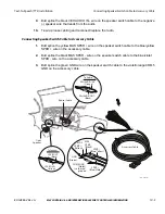
Locate the J1939 CAN wires on the MCP100 accessory cable. These are usually
located either in the truck’s B pillar or in the center of the dash.
2.
Connect J1939 CAN wires to truck’s J1939 stub.
3.
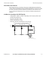
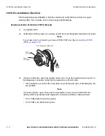
If a stub does not exist, splice directly into the J1939 backbone. Locate a connector
point and Ohm out (0 Ohms) CAN + and CAN - wires to Pin C (CAN high) and Pin D
(CAN low) on the diagnostic connector.
4.
Measure the J1939 bus resistance at the diagnostic connector. It should read 60 ohms.
5.
Start the vehicle and verify that the truck is in good working order and displays no dash
faults.
6.
Verify that the J1939 data is being passed to the MAS from the data bus by monitoring
the VDS screen on the MAS. (Refer to
Verifying Data Source Connectivity
.)
7.
Stow and secure any loose wires, making sure to keep the wires clear of sharp edges
and away from panels and moving parts.


