Panic Wire Installation
Wireless Panic Button Installation
22-6
MAY CONTAIN U.S. AND INTERNATIONAL EXPORT CONTROLLED INFORMATION
80-J4866-2 Rev. G
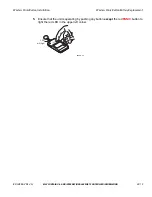
4.
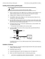
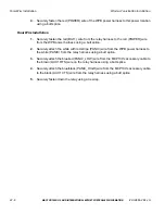
Securely fasten the red (POWER) wire of the WPB power harness to this power location
using a butt splice.
Panic Wire Installation
1.
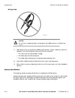
Securely fasten the red (BAT+) wire from the relay harness to the red (POWER) wire
from the WPB power harness using a butt splice.
2.
Securely attach the white with red stripe (PANIC) wire from the WPB power harness to
the white (PANIC) from the relay harness using a butt splice.
3.
Securely attach the blue/red (PANIC_LOW) wire from the MCP100’s accessory cable to
the brown (AUX1 RTS) wire on the relay harness using a butt splice.
4.
Securely attach the blue/black (PANIC_HIGH) wire from the MCP100’s accessory cable
to the black (AUX1 CTS) wire from the relay harness using a butt splice.
5.
Securely fasten down the relay using a tie wrap.


