80-J4866-2 Rev. G
MAY CONTAIN U.S. AND INTERNATIONAL EXPORT CONTROLLED INFORMATION
11-5
Vehicle Data Bus Connections
Checking the MCP100 Accessory Cable
Checking the MCP100 Accessory Cable
1.
Locate the end of the installed MCP100 accessory cable to determine which option
applies.
2.
Locate the CAN connector on the accessory cable.
3.
If it is a 6-pin Molex connector, go to
Option 1—Connecting J1939 Using the Repeater
4.
If it is a 4-pin Molex connector, go to
Option 2—Connecting J1939 Using the Converter
5.
If there is no Molex connector present, go to
Option 3—Connecting Directly to J1939
Option 1—Connecting J1939 Using the Repeater Cable
Use the repeater cable when the distance between the MAS and J1939 bus connection point
exceeds 10 feet. Also use option 1 for any after market installations.
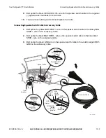
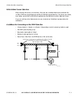
Connect the MCP100 accessory cable to the CAN repeater. A CAN repeater cable
is
required
for this procedure (see
for detailed pin and wire callouts of the CAN
repeater cable).
Mobile Application Server
(MAS)
REPEATER
08AAA_048
To Modem
To Display
J1939+
Yellow
J1939-
Green
J1939+
J1939-
MCP
Accessory Cable
Accessory
Cable
D
E
F
G
H
J
B
C
A
CAN_H
CAN_L
Termination resistors
at the far ENDS of
the Main Backbone
Each120 Ohms 5% 1/4W
TRUCK ECM
6-pin Molex connector
Most US ECMs are
hi impedance (Z)
and not internally terminated
PIN C
CAN_HIGH
PIN D
CAN_LOW
Diagnostic
Connector
PIN 4
PIN 4
PIN 4
PIN 1
PIN 1
PIN 1
PIN 6
PIN 6
PIN 6
PIN 3
PIN 3
PIN 3

