Page 14
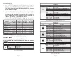
4) Connect Cables
a. Insert the SFP/SFP+ transceiver into the SFP receptacle on the front of
the module (see the SFP Data Sheet 091-17000-001 for supported Gigabit
transceivers or 091-17400-001 for supported 10G transceivers).
NOTE: The release latch of the SFP fiber transceiver must be in the closed
(up) position before insertion.
b. Connect an appropriate multimode or single-mode fiber cable to the fiber port
on the front of the module. It is important to ensure that the transmit (TX) is
attached to the receive side of the transceiver at the other end and the receive
(RX) is attached to the transmit side. When using single-fiber (SF) models, the
TX wavelength must match the RX wavelength at the other end and the RX
wavelength must match the TX wavelength at the other end.
c. Connect the Ethernet 10/100/1000 RJ-45 port using a Category 5 or better
cable to an external 10BASE-T, 100BASE-TX or 1000BASE-T Ethernet device.
Description
15W
IEEE 802.3af
PoE
30W
IEEE 802.3at
PoE+
60W
IEEE 802.3.bt
PoE (Type 3)
100W
IEEE 802.3bt
PoE (Type 4)
Power Supply Voltage
Range
46.0 to 57.0 VDC 51.0 to 57.0 VDC 51.0 to 57.0 VDC 53.0 to 57.0 VDC
Voltage Range at PSE
port Output
44.0 to 56.0 VDC 50.0 to 56.0 VDC 50.0 to 56.0 VDC 52.0 to 56.0 VDC
Maximum Power from
PoE/PSE port
15.4 watts
30 watts
60 watts
100 watts
Minimum Voltage at
PoE/PD port input*
37.0 VDC
42.5 VDC
42.5 VDC
41.1 VDC
Minimum Power at
PoE/PD port*
12.95 watts
25.5 watts
51 watts
71 watts
* at 100 meters using Cat5
PoE, PoE+ and 802.3bt Requirements
5) Verify Operation
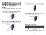
Verify the module is operational by viewing the LED indicators.
NOTE: The PSE LED may turn Amber (ON) when a non-PD device is connected
to the port.
Power
LED Indicators
Legend
Indicator
Description
Pwr A
and
Pwr B
OFF
Unit not powered
Green - ON
Unit powered
Green - Blinking at 1Hz
Unit powered and Reset button has been depressed.
Power LED Indicators
Page 13
Uplink
LED Indicators
Legend
Indicator
Description
1000
(Link)
OFF
Port not linked
Green - ON
Port linked at the speed indicated by the Speed LED
Green - Blinking at 10Hz Port is transmitting or receiving data
Green - Blinking at 1Hz
Port in redundant secondary mode
10G
(Speed)
OFF
Port not linked
Amber - Blinking at 1Hz
Port not linked and receiving remote fault or FEFI
Green - single blink
Port linked at 10M, 100M or 1G
Green - two blinks
Port linked at 2.5G
Green - three blinks
Port linked at 5G
Green - four blinks
Port linked at 10G
SFP/Uplink Ports LED Indicators LED Indicators
RJ-45 User Ports
LED Indicators
Legend
Indicator
Description
100
OFF
No link
Green - ON
Port linked at 100Mbps
Green - Blinking at 10Hz Port data activity at 100Mbps
Amber -ON
Port linked at 100Mbps Half-duplex
Amber - Blinking at 10Hz Port data activity at 100Mbps Half-duplex
1000
OFF
No link
Green - ON
Port linked at 1000Mbps
Green - Blinking at 10Hz Port data activity at 1000Mbps
Amber -ON
Port linked at 1000Mbps Half-duplex
Amber - Blinking at 10Hz Port data activity at 1000Mbps Half-duplex
10
OFF
No link
Green - ON
Port linked at 10Mbps
Green - Blinking at 10Hz Port data activity at 10Mbps
Amber -ON
Port linked at 10Mbps Half-duplex
Amber - Blinking at 10Hz Port data activity at 10Mbps Half-duplex
PoE/PSE LED Indicators are located next to the RJ-45 User Ports
PoE/PSE
OFF
Port PSE inactive
Amber - ON
Port PSE inactive - exceeding the power source
Green - single blink
Powered by 802.3af PoE 15W
Green - two blinks
Powered by 802.3at PoE 30W
Green - three blinks
Powered by High-Power PoE 60W
Green - four blinks
Powered by High-Power PoE 100W
RJ-45 LED Indicators

