


13
•
EN
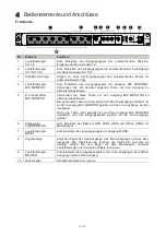
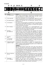
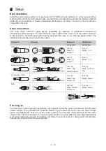
Rear panel
No.
Element
Function
11
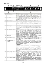
AC power input
Use the included power cable to connect this input to a power outlet.
Alternatively, use the DC power input via the screw terminals. If both
inputs are used, the device will draw its power from the AC power input.
12
Fuse holder
Only replace the fuse when the device is disconnected from mains. Only
use fuses of the same rating and power. The correct fuse value is
specified on the rear panel.
13
DC power input
Screw terminals for alternative power supply from a 24V source.
14
Line outputs
These stereo outputs carry the master signal and are on balanced XLR
jacks. Use standard XLR cables to connect these outputs to your active
speakers or amplifiers. The output level is set by the MASTER control
(9).
15
Mono output
Unbalanced mono 6.3 mm output carrying a summed mono signal of the
line outputs. Use a standard 6.3 mm cable to connect further amplifiers
or other units with line level input. The output level is set by the MONO
control (7).
16
MIC MONITOR output
Unbalanced mono 6.3 mm output for connecting a monitoring system.
The output level is set by the MIC MONITOR control (4). When the MIC
ON/OFF button (5) is depressed, the signal from the mic/line inputs
(channel 1-6) will be sent to this output, and the line outputs will be
disabled. When the MIC ON/OFF button is raised, this output will be
disabled, and all channels will be sent to the line outputs.
17
REC output
Unbalanced stereo RCA output for connecting a remote recording
device. The recording level is set by the MASTER control (9).
18
CH 7/8-11/12 line inputs Unbalanced stereo RCA inputs for channel 7/8-11/12. Use standard
stereo RCA cables to connect line-level devices (e.g. CD player) to
these inputs.
19
LINE/PP 21V/MIC input
selectors
Use these switches to set what type of audio source is connected to
each mic/line input of the mono channels 1-6: a line-level device (LINE),
a microphone without phantom power (MIC), or a microphone with +18-
21V phantom power (PP 21V).
Caution!
If phantom power is switched on, no unbalanced microphones or
devices with line level must be connected to the corresponding inputs.
Otherwise, these devices may be damaged. During the stabilization
phase (approx. 1 minute), you must not connect or disconnect any
microphones. To prevent switching noise, only switch on phantom
power when the mixer is switched off or when all output controls are set
to minimum.
20
CH 1-6 mic/line inputs
Balanced combo XLR and 6.3 mm jack connectors for the mono
channels 1-6. Use standard XLR or 6.3 mm cables to connect
microphones or line-level devices to these inputs. Channel 1 has
priority: when this channel receives an incoming signal (e.g.
announcement), the level of the other channels is attenuated—
depending on the CH 1 PRIORITY (21) control.
21
CH 1 PRIORITY control
Adjusts the attenuation level of all other inputs, when channel 1 receives
an incoming signal. At its lowest setting, all other channels will be muted
entirely. At its highest setting, the other input signals will not be affected
by a signal at channel 1 at all.
MIC/LINE INPUTS
24V 500mA
AC INPUT: 230V 50Hz 12W
~
FUSE: T500mAL AC 250V
LINE OUT
MONO
OUT
MIC
MONITOR
OUT
REC OUT
CH 11/12
CH 9/10
CH 7/8
LINE INPUTS
R
L
CH6
CH 1
PRIORITY
PP 21V
PP 21V
PP 21V
PP 21V
PP 21V
PP 21V
MIC/LINE INPUTS
R
L
L
R
LINE
LINE
LINE
LINE
LINE
LINE
MIC
MIC
MIC
MIC
MIC
MIC
CH 6
CH 5
CH 4
CH 3
CH 2
CH 1
L
R
21
11
13
14
15 16
17
18
19
12
20
Summary of Contents for EM-312
Page 1: ...1 DE...