background image


14 

 EN 

5

  Setup


Rack installation 

Install the unit on a plane surface or in your rack. For 19" (483 mm) rack installation, 1 unit is required. When 
mounting the unit into the rack, please make sure that there is enough space around the device so that the 
heated  air  can  be  passed  on.  Steady  overheating  will  damage  your  device.  You  can  fix  the  unit  with  four 
screws M6 in the rack. 
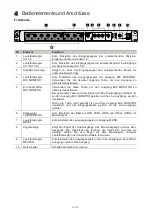
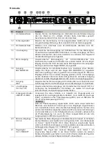
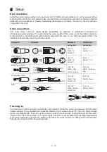
 

Cable connections 

The  mixer  offers  numerous,  highly  flexible  possibilities  for  balanced  or  unbalanced  connection  of 
professional  audio  equipment.  To  avoid  interfering  noise,  switch  off  the  mixer  or  set  the  output  controls  to 
minimum  prior  to  connecting  and  disconnecting  equipment.  Be  sure  to  use  only  high-grade  cables.  The 
illustrations below show the wiring of these cables.  
 

Connector 

Structure 

Balanced 

connection 

Unbalanced 

connection 

XLR, male. 


red = 2 
black = 3 
shield = 1 


red = 2 
shield = 1 + 3 

XLR, female 


red = 2 
black = 3 
shield = 1 


red = 2 
shield = 1 + 3 

6.3mm jack, stereo 


red = tip 
black = ring 
shield = sleeve 


red = tip 
shield  =  sleeve  + 
ring  

6.3 mm jack, mono 


red = tip 
black = ring 
shield = n/c 


red = tip 
shield = sleeve 

RCA 


red = tip 
black = sleeve 
shield = n/c 


red = tip 
shield = sleeve 


Powering up 

To  protect  your  audio  equipment,  specifically  your  speakers,  follow  this  power-up  sequence:  Set  all  output 
volume  controls  of  any  equipment  to  minimum.  Switch  on  your  audio  sources  first,  then  the  mixer.  Always 
switch  on  amplifiers  last.  Then  turn  up  the  volume  control  on  your  sources  (if  provided)  and  set  the  output 
volume of the mixer to a low level. Turn up the volume controls of your amplifier(s) slowly. Make adjustments 
to all volume settings as needed. For switching off, follow the inverse sequence: always switch off amplifiers 
first, then the mixer and then the audio sources.  


Summary of Contents for EM-312

Page 1: ...1 DE...

Page 2: ...M 312 bietet separate Lautst rkeregler f r alle Eing nge einen Lautst rkeregler f r den Monoausgang und einen Master Regler sowie einen 3 Band Equalizer Zur besseren Verst ndlichkeit einer Durchsage i...

Page 3: ...belastet werden Es muss stets eine ausreichende Kabell nge zum Ger t hin vorhanden sein Andernfalls kann das Kabel besch digt werden was zu t dlichen Stromschl gen f hren kann Achten Sie darauf dass d...

Page 4: ...berspannung k nnte das Ger t zerst ren Das Ger t bei Gewitter allpolig vom Netz trennen Netzstecker ziehen Das Ger t darf nicht in einer Umgebung eingesetzt oder gelagert werden in der mit Spritzwasse...

Page 5: ...wird der Ausgang MIC MONITOR deaktiviert und alle Eingangskan le werden an die Line Ausg nge geleitet 6 Klangregler LOW MID HIGH Zum Einstellen der B sse LOW Mitten MID und H hen HIGH im Mastersignal...

Page 6: ...Buchsen f r Kanal 7 8 11 12 Verwenden Sie handels bliche Cinch Kabel um Ger te mit Line Pegel z B CD Player an diese Eing nge anzuschlie en 19 Eingangsumschalter LINE PP 21V MIC Verwenden Sie diese S...

Page 7: ...hluss Unsymmetrischer Anschluss XLR m nnl Rot 2 Schwarz 3 Schirm 1 Rot 2 Schirm 1 3 XLR weibl Rot 2 Schwarz 3 Schirm 1 Rot 2 Schirm 1 3 6 3 mm Klinke stereo Rot Spitze Schwarz Ring Schirm Schaft Rot S...

Page 8: ...die Anschlussleitung dieses Ger tes besch digt wird muss sie durch den autorisierten Fachhandel ersetzt werden um Gef hrdungen zu vermeiden Sollten Sie noch weitere Fragen haben steht Ihnen Ihr Fachh...

Page 9: ...tput for the mic section The EM 312 offers separate volume controls for all inputs in addition to volume control for the mono output and a master volume control It has a 3 band equalizer and an adjust...

Page 10: ...to power cord damages fire or mortal electrical shock The cable insert or the female part in the device must never be strained There must always be sufficient cable to the device Otherwise the cable...

Page 11: ...age could destroy the device Always disconnect the device during thunderstorms This device must never be operated or stockpiled in surroundings where splash water rain moisture or fog may harm the dev...

Page 12: ...and all channels will be sent to the line outputs 6 LOW MID HIGH tone controls Use these controls to adjust the bass frequencies LOW mid range frequencies MID and high frequencies HIGH of the main mi...

Page 13: ...for channel 7 8 11 12 Use standard stereo RCA cables to connect line level devices e g CD player to these inputs 19 LINE PP 21V MIC input selectors Use these switches to set what type of audio source...

Page 14: ...ctor Structure Balanced connection Unbalanced connection XLR male red 2 black 3 shield 1 red 2 shield 1 3 XLR female red 2 black 3 shield 1 red 2 shield 1 3 6 3mm jack stereo red tip black ring shield...

Page 15: ...s to be replaced by a special power supply cable available at your dealer Should you have further questions please contact your dealer 7 Technical Specifications EM 312 Power supply 230 V AC 50 Hz or...

Page 16: ...OMNITRONIC 2019 D00121887 Version 1 0 Omnitronic is a brand of Steinigke Showtechnic GmbH Andreas Bauer Str 5 97297 Waldb ttelbrunn Germany...

Reviews: