


15
1
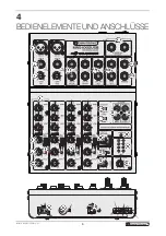
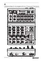
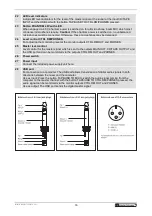
Microphone input MIC IN
Balanced XLR connector for the mono channels to connect a microphone. For condenser
microphones, a 48 V phantom power can be activated with the PHANTOM 48V switch.
2
Input LINE IN
Balanced 6.3 mm jack for the mono channels to connect audio units with line level (e.g. musical
instrument).
3
Input LINE IN
Balanced 6.3 mm jacks L/R for the stereo channels to connect audio units with line level (e.g.
musical instrument). When connecting a mono device, only use the upper jack L/MONO.
4
Control GAIN
For adjusting the input amplification of the microphone and line input of the mono channels.
5
Tone controls
For adjusting the high frequencies (HIGH), mid-frequencies (MID) and bass frequencies (LOW).
6
Control AUX SEND
To add the channel signal to the effect send way which is available at the output AUX SEND.
7
Panorama control
To place the mono signal in the stereo sound for the mono channels.
8
CLIP indicator
9
Balance control
For adjusting the balance left/right for the stereo signal for the stereo channels.
10
Level control
To add the channel signal to the master signal.
11
Input STEREO AUX RETURN
Input (6.3 mm jacks L/R, unbal.) for connecting an effect unit or an additional line audio source.
When connecting a mono device, only use the left jack L/MONO.
12
Output CTRL RM OUT
Output (6.3 mm jacks L/R, unbal.) for connecting an amplifier of a monitor system.
13
Output MAIN OUT
Main output (6.3 mm jacks L/R, unbal.) for the master signal for connecting an amplifier or a
second mixer.
14
Output AUX SEND
Mono output (6.3 mm jacks, unbal.) for connecting the input of an effector.
15
Headphones output
6.3 mm jack for connecting stereo headphones (min. impedance 8
Ω
).
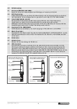
16
Button TAPE TO CTRL RM/PHONES
With the button pressed, the signal at the input CD/TAPE INPUT and the USB port is sent to the
monitoring outputs CTRL RM OUT and PHONES and indicated by the LED level indicators.
17
Button TAPE/USB TO MIX
With the button pressed, the signal at the input CD/TAPE INPUT and the USB port is sent to the
master channel
18
Input CD/TAPE INPUT
Stereo input (RCA L/R) for connecting the output of a recorder or another playback unit (e.g. CD
player).
19
Output CD/TAPE OUT
Stereo output (RCA L/R) of the master signal for connecting the input of a recorder or an amplifier.
20
Power indicator
21
Level control MASTER AUX SEND
Level control for the total signal of the effect way at the output AUX SEND.
Summary of Contents for MRS-1002USB
Page 1: ......
Page 6: ...6 4 BEDIENELEMENTE UND ANSCHL SSE...