background image


17

SETTING INTO OPERATION 

Switching on and off 

Prior  to  switching  on,  turn  the  output  controls  MASTER  LEVEL  und  CTRL  RM  to  minimum  to  avoid 
damage to the hearing by a volume which is too high when switching on.  

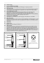
If  condenser  microphones  are  connected,  press  the  button  PHANTOM  48V  to  switch  on  a  48  V 
phantom power for all XLR jacks. The indicator next to the button lights up. 

Switch  on  the  mixer  with  the  power  switch.  The  power  indicator  lights  up.  Switch  on  the  connected 
units. After operation, switch off the unit with the power switch.  


Basic control 

For even sound, every input channel should be adjusted to the same level. Follow this procedure for every 
input channel: 


Set the gain control, the level control, the tone controls and the pan/balance control to mid-position.  

Feed an audio signal (test signal or music) to the input channel. 

Adjust  the  MASTER  LEVEL  control  for  the  overall  volume  to  a  level  that  the  subsequent  adjustments 
can be heard well via a connected PA system.  

For a mono channel, adjust the gain control so that the level indication lights up at 0 dB. For a stereo 
channel, turn up the level control so that the level indication lights up at 0 dB. 

Adjust  the  desired  sound  with  the  tone  controls.  By  adjusting  the  tone  controls,  the  high  frequencies 
(control HIGH), the mid frequencies (control MID) and the low frequencies (control LO) can be boosted 
or attenuated. With the controls in mid-position, the frequency response is not affected. 

For  the  mono  channels,  place  the  mono  signals  in  the  stereo  sound  with  the  panorama  control  PAN, 
and for the stereo channels, adjust the balance of the stereo signals with the control BAL. 

The  LED  CLIP  serves  as  an  overload  indication  by  which  the  level  of  the  channel  can  coarsely  be 
controlled. If it lights up permanently, attenuate the input amplification and/or turn back the tone controls 
or reduce the output level of the audio source. 

Repeat the steps for other channels as described above. 

When all adjustments for level matching and all sound adjustments have been made, mix the signals of 
all audio sources used in the desired volume ratio with the level controls. 

10 

Via  the  output  meter,  adjust  the  desired  level  available  at  the  master  outputs  with  the  master  level 
control. Usually an optimum level control is obtained if the output meter shows values in the 0 dB range 
at average volume. However, if the output level at the master outputs is too high for the following unit, 
the master signal must be controlled to a corresponding lower level. In case of overload the red LEDs 
CLIP light up. 


CAUTION! 


• If  the  phantom  power  is  switched  on,  no  microphones  with  unbalanced  output  must  be 

connected.  Otherwise  these  microphones  may  be  damaged.  During  the  stabilization  phase 
(approx. 1 minute), you must not change any connection. 


• To prevent switching noise, only  actuate  the button PHANTOM POWER when the mixer is 

switched off or when the output level controls are set to minimum. 


Summary of Contents for MRS-1002USB

Page 1: ......

Page 2: ...r Pr zise 4 stellige Stereo LED Pegelanzeige Spannungsversorgung ber mitgeliefertes Netzteil Stabiles kompaktes Metallgeh use Compact Audio Mixer Compact audio mixer with 6 inputs and USB interface Bu...

Page 3: ...MENTE UND ANSCHL SSE 6 5 INBETRIEBNAHME 9 6 REINIGUNG UND WARTUNG 11 7 TECHNISCHE DATEN 11 Table of Contents 1 INTRODUCTION 12 2 SAFETY INSTRUCTIONS 12 3 OPERATING DETERMINATIONS 13 4 OPERATING ELEMEN...

Page 4: ...r Garantieanspruch F r daraus resultierende Folgesch den bernimmt der Hersteller keine Haftung Bitte berpr fen Sie vor der ersten Inbetriebnahme ob kein offensichtlicher Transportschaden vorliegt Soll...

Page 5: ...on direkter Sonneneinstrahlung auch beim Transport in geschlossenen W gen und Heizk rpern fern Die maximale relative Luftfeuchte betr gt 100 bei einer Umgebungstemperatur von 25 C Dieses Ger t darf nu...

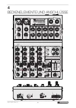
Page 6: ...6 4 BEDIENELEMENTE UND ANSCHL SSE...

Page 7: ...TEREO AUX RETURN Eingang 6 3 mm Klinkenbuchsen L R unsym zum Anschluss eines Effektger ts oder einer zus tzlichen Line Tone quelle Verwenden Sie bei Anschluss eines Mono Ger ts nur die linke Buchse L...

Page 8: ...er CTRL RM PHONES Zum Einstellen der Lautst rke an den Abh rausg ngen CTRL RM OUT und PHONES 25 Master Pegelregler Pegelregler f r das Mastersignal das ber die Buchsen MAIN OUT CD TAPE OUTPUT und die...

Page 9: ...w stark senken Stehen die Regler in Mittelstellung findet keine Frequenzgangbeeinflussung statt 6 Verwenden Sie f r die Mono Kan le den Panoramaregler PAN um die Mono Signale im Stereo Klangbild platz...

Page 10: ...rbunden ist das ber das Netzkabel geerdet ist z B Verst rker k nnen aufgrund von Masseschleifen Brummst rungen auftreten Um diese St rungen zu beseitigen verbinden Sie den Mixer ber einen Massetrennfi...

Page 11: ...0 Hz ber mitgeliefertes Netzteil Gesamtanschlusswert 27 W Eing nge Empfindlichkeit 2 x Mic mono 0 5 mV XLR symmetrisch 2 x Line In mono 1 mV Klinke symmetrisch 2 x Line In stereo 10 mV Klinke L R symm...

Page 12: ...not accept liability for any resulting defects or problems Please make sure that there are no obvious transport damages Should you notice any damages on the power unit or on the casing do not take the...

Page 13: ...eep away from direct insulation particularly in cars and heaters The relative humidity must not exceed 100 with an ambient temperature of 25 C This device must only be operated in an altitude between...

Page 14: ...14 4 OPERATING ELEMENTS CONNECTIONS...

Page 15: ...Input STEREO AUX RETURN Input 6 3 mm jacks L R unbal for connecting an effect unit or an additional line audio source When connecting a mono device only use the left jack L MONO 12 Output CTRL RM OUT...

Page 16: ...r outputs CTRL RM OUT and PHONES 25 Master level control Level control for the master signal which is sent to the outputs MAIN OUT CD TAPE OUTPUT and the USB port and can be monitored via the outputs...

Page 17: ...ted or attenuated With the controls in mid position the frequency response is not affected 6 For the mono channels place the mono signals in the stereo sound with the panorama control PAN and for the...

Page 18: ...mains cable e g amplifier noise interference may occur due to ground loops To eliminate this interference a ground isolator e g OMNITRONIC LH 082 may be used to connect the mixer to the unit Adjustin...

Page 19: ...ts sensitivity 2 x Mic mono 0 5 mV XLR bal 2 x Line In mono 1 mV 6 3 mm jack bal 2 x Line In stereo 10 mV 150 mV RCA L R 1 x Stereo Aux Return 100 mV 6 3 mm jack L R bal 1 x Tape In 100 mV RCA L R Out...

Page 20: ...OMNITRONIC 201 OMNITRONIC 201 OMNITRONIC 201 OMNITRONIC 2014 4 4 4 Technische nderungen und Irrtum vorbehalten Every information is subject to change without prior notice 00083727 DOCX Version 1 0...

Reviews: