background image

00041735.DOC, Version 2.0

23/27

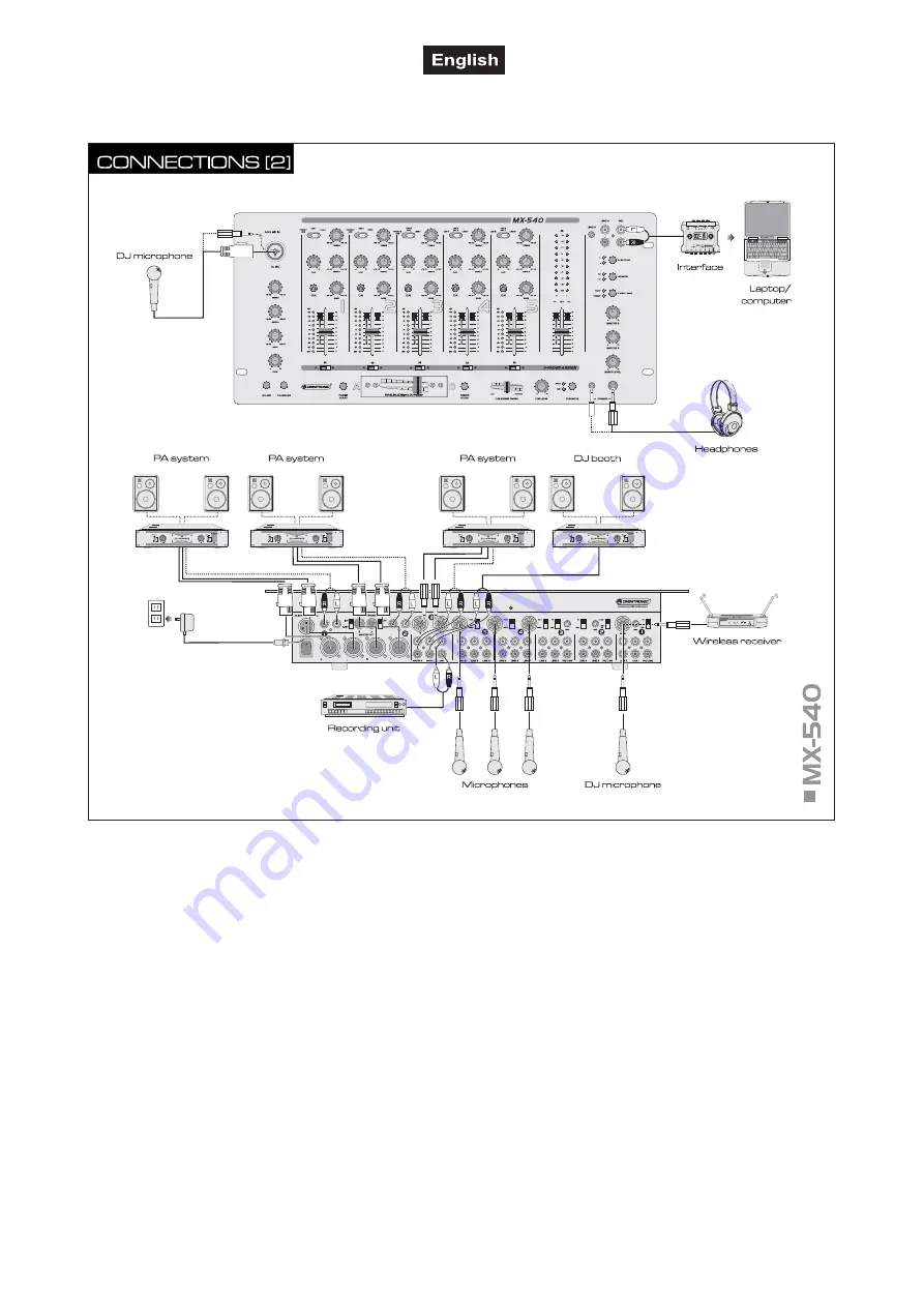
2  CD players with contact control can be remote controlled with the crossfader of the 

MX-540

 (fader

start function). Connect each unit to the corresponding 3.5 mm jack X-FADER START of the mixer.

3  You can connect four microphones: a DJ microphone to the DJ microphone channel DJ MIC and three

further microphones to the microphone channel MIC 1, MIC 2 and MIC 3.
• Connect a DJ microphone via an XLR plug or a 6.3 mm plug to the front input DJ MIC or via 6.3 mm

plug to the rear input DJ MIC. When connecting a microphone to the rear input, the control LED REAR
MIC IN lights at the front panel. With the rear input selector switch it is possible to switch the
microphone input DJ MIC to line input for mono units with line level output (e.g. wireless receivers)

• Three further microphones can be connected via 6.3 mm plugs to the rear inputs MIC 1, MIC 2 and

MIC 3.

4  For connecting amplifiers, several stereo outputs with individual level controls are available:

• Connect the main amplifiers to the outputs MASTER 1, MASTER 2 and MASTER 3, optionally to the

balanced XLR or 6.3 mm output or to the unbalanced RCA output.

• If a monitoring system is available, connect the amplifier of the monitoring system to the stereo output

BOOTH.

5  For analog sound recordings, connect the recording units to the outputs REC(ORD). The recording level

is independent of the position of the master fader and the output controls MASTER 2, MASTER 3 and
BOOTH LEVEL. With an audio interface such as the 

OMNITRONIC DDI 4x4

 you can also digitize

the analog output signal of the 

MX-540

 and transfer it to a computer with USB 1.1 or 2.0 connection.

6  For prefader listening to the input channels or for monitoring the current music program ahead of the

master fader and the output controls MASTER 2, MASTER 3 and BOOTH LEVEL, it is possible to
connect stereo headphones to the front input PHONES, optionally via 3.5 mm plug or 6.3 mm plug.

Summary of Contents for MX-540

Page 1: ...Copyright Nachdruck verboten Reproduction prohibited F r weiteren Gebrauch aufbewahren Keep this manual for future needs BEDIENUNGSANLEITUNG USER S MANUAL MX 540 Multichannel Mixer...

Page 2: ...00041735 DOC Version 2 0 2 27...

Page 3: ...TRUCTIONS 16 3 OPERATING DETERMINATIONS 17 4 DESCRIPTION 18 4 1 Features 18 4 2 Operating elements and connections 19 5 INSTALLATION 22 5 1 Rack installation 22 5 2 Connections 22 6 OPERATION 24 6 1 B...

Page 4: ...n Wenn Sie nachfolgende Hinweise beachten sind wir sicher dass Sie lange Zeit Freude an Ihrem Kauf haben werden Nehmen Sie das Ger t aus der Verpackung 2 SICHERHEITSHINWEISE Dieses Ger t hat das Werk...

Page 5: ...Servicearbeiten sind ausschlie lich dem autorisierten Fachhandel vorbehalten 3 BESTIMMUNGSGEM SSE VERWENDUNG Der Multichannel Mixer MX 540 f r drei Beschallungszonen verf gt ber f nf Stereo Eingangska...

Page 6: ...angskan le mit Gainregler 3 Band Equalizer Cue Taste leichtg ngigen langlebigen Fadern und 10 stelliger LED Pegelanzeige 1 DJ Mikrofonkanal mit 3 Band Equalizer Lautst rkeregler On Air und Talkover Sc...

Page 7: ...chalter f r den DJ Mikrofonkanal Bei gedr ckter Taste rote LED leuchtet ist das DJ Mikrofon einge schaltet 8 Talkover Ein Aus Ein Ausschalter f r die Talkoverfunktion Bei gedr ckter Taste blaue LED le...

Page 8: ...2 MASTER 3 und BOOTH abgeh rt 14 Lautst rkeregler CUE LEVEL Lautst rkeregler f r den Kopfh rerausgang 15 Umschalter CUE MODE W hlt den Abh rmodus f r den Kopfh rerausgang SPLIT Taste gedr ckt rote LE...

Page 9: ...die Anschlussleitung des beiliegenden Netzteils ein und fixieren Sie sie mit der berwurfmutter 31 Netzschalter Dr cken Sie den Netzschalter um das Ger t ein und auszuschalten 32 Masterausg nge Stereo...

Page 10: ...eren Ger ten vorhanden ist Dauerhafte berhitzung kann zu Sch den am Ger t f hren Sie k nnen das Ger t mit vier Schrauben M6 im Rack befestigen 5 2 Anschl sse Schalten Sie das Mischpult vor dem Anschli...

Page 11: ...itigen Eingang leuchtet zur Kontrolle die LED REAR MIC IN auf der Frontplatte Der Mikrofoneingang DJ MIC l sst sich mit dem r ckseitigen Umschalter f r Mono Ger te mit Line Pegel Ausgang auf Line Eing...

Page 12: ...nal kann auch ber einen Kopfh rer abgeh rt werden lesen Sie dazu Abschnitt 6 6 5 Die Kanal Pegelanzeige zeigt den Pegel vor dem Kanalfader Prefader Pegel an Steuern Sie anhand der Pegelanzeige mit dem...

Page 13: ...t rot 2 Stellen Sie mit dem Regler LEVEL die Lautst rke der Mikrofondurchsage ein 4 Stellen Sie mit dem 3 Band Equalizer das gew nschte Klangbild ein Durch Verstellen der Klangregler lassen sich die H...

Page 14: ...ten FADER START Kontroll LEDs aus 7 REINIGUNG UND WARTUNG Vor Wartungsarbeiten unbedingt allpolig vom Netz trennen LEBENSGEFAHR Das Ger t sollte regelm ig von Verunreinigungen wie Staub usw gereinigt...

Page 15: ...ASTER 3 Stereo Cinch 6 3 mm Stereo Klinke Ausgangsspannung 0 75 V RMS BOOTH Stereo Cinch Ausgangsspannung 0 75 V RMS REC Stereo Cinch Ausgangsspannung 0 75 V RMS Kopfh rer 3 5 mm 6 3 mm Klinke 8 X FAD...

Page 16: ...acquired a reliable and powerful device If you follow the instructions given in this manual we can assure you that you will enjoy this device for many years Unpack your mixer 2 SAFETY INSTRUCTIONS Th...

Page 17: ...iceable parts inside the device Maintenance and service operations are only to be carried out by authorized dealers 3 OPERATING DETERMINATIONS The multichannel mixer MX 540 for three PA zones features...

Page 18: ...igit LED level meter 1 DJ microphone channel with 3 band equalizer level control on air and talkover selector Prefader listening to all input channels and the master output via adjustable headphones o...

Page 19: ...crophone channel With the button pressed red LED lights the DJ microphone is switched on 8 Talkover on off On off switch for the talkover function With the button pressed blue LED lights the levels of...

Page 20: ...f the master fader and the output controls MASTER 2 MASTER 3 and BOOTH LEVEL 14 Level control CUE LEVEL Level control for the headphones output 15 Selector switch CUE MODE For selecting the monitoring...

Page 21: ...its with line level outputs e g CD players 36 Inputs PH LINE Stereo inputs RCA for the channels 1 3 for connecting turntables with magnetic system With the corresponding input selector switches the in...

Page 22: ...l damage your device You can fix the unit with four screws M6 in the rack 5 2 Connections Switch off the mixer prior to connecting any units or to changing any existing connections 1 Connect the stere...

Page 23: ...s MIC 1 MIC 2 and MIC 3 4 For connecting amplifiers several stereo outputs with individual level controls are available Connect the main amplifiers to the outputs MASTER 1 MASTER 2 and MASTER 3 option...

Page 24: ...an be boosted 12 dB max or substantially attenuated 26 dB max With the controls in mid position the frequency response is not affected Sound adjustments affect the level Readjust the channel level wit...

Page 25: ...ls 1 5 via headphones even if the corresponding channel is faded out Thus it is possible e g to time the moment for fading in an audio source Alternatively it is possible to monitor the current music...

Page 26: ...serviceable parts inside the device Maintenance and service operations are only to be carried out by authorized dealers Should you need any spare parts please use genuine parts Should you have furthe...

Page 27: ...itchable MASTER 3 stereo RCA 6 3 mm stereo jack Output voltage 0 75 V BOOTH stereo RCA Output voltage 0 75 V REC stereo RCA Output voltage 0 75 V Headphones 3 5 mm 6 3 mm jack 8 X FADER START 2x 3 5 m...

Reviews: