252
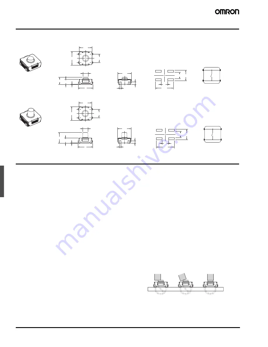
Middle Stroke Tactile Switch
B3SL
Dimensions
Note:
Unless otherwise specified, all units are in millimeters and a tolerance of
±
0.2mm applies to all dimensions.
B3SL-1002P
B3SL-1022P
Precautions
■
Precautions for Correct Use
Storage
Storage Environment
To prevent degradation, such as discoloration of the terminals during
storage, do not store the Switch in locations that are subject to the
following conditions;
•
High temperature or humidity
•
Corrosive gases
•
Direct sunlight
Storage condition
Store the Switches in the packaging box.
After the packaging box is opened, use the contents as quickly as
possible. When storing leftover parts, make sure that appropriate
measures are taken against humidity and corrosive gases.
Handling
Usage Environment
Before installing the Switch, make sure that the area of installation is
not subject to corrosive gases emitted from surrounding parts.
1.
Do not use in areas subject to high temperatures, high humid-
ity, or toxic gases such as sulfuric gas (H
2
S, SO
2
), ammonia
gas (NH
3
), nitric gas (HNO
3
), or chlorine gas (CI
2
). It can
cause corrosive damage to the contacts and result in mal-
function.
2.
If there is silicon in the atmosphere, it may stop the contacts
from functioning properly. If silicon products, such as silicon
oil, silicon filler, or silicon wires, are used in the surrounding
area, install a contact protection circuit to prevent arching or
remove the silicon source. The Switch is not completely
sealed. The following situations may cause water to enter
inside the Switch, resulting in a malfunction due to contact
failure or corrosion.
•
Using the Switch in an outdoor environment where it is
exposed to water drops for an extended period of time
•
Using the Switch in an underwater setting where it is sub-
ject to strong water pressure.
Operation
•
Do not repeatedly operate the Switch with excessive force.
Applying excessive pressure or applying additional force after the
plunger has stopped may deform the disk spring of the Switch,
resulting in malfunction. (Maximum force = 30N)
•
Be sure to set up the Switch so that the plunger will operate in a
straight vertical line. If the plunger is pressed off-center or from an
angle it may cause deformation or damage to some parts. This may
result in deterioration of life expectancy or malfunction.
4
±
0.2
6.2
6.5
0.1
7
6.5
1.2
3
3
8.5
5
0.7
2.5 dia.
3.4
2.5
4
2
3
1
PCB Pad
(Top View)
Terminal Arrangement/
Internal Connections
(Top View)
4
±
0.2
6.2
6.5
3
3
8.5
5
6.5
1.2
0.7
0.1
7
2.5 dia.
5.1
2.5
4
2
3
1
PCB Pad
(Top View)
Terminal Arrangement/
Internal Connections
(Top View)


