1 Preparation
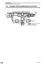
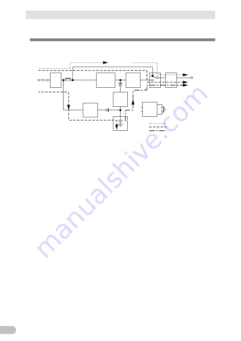
1-5 Diagram of the Input/output circuit block
BU150R
20
1-5 Diagram of the Input/output circuit block
Noise
filter
Input
overcurrent
protection
AC100V
input
Power
supply
relay
Charging
circuit
Rectifier
(high power
factor
converter)
Step-up
converter
Inverter
(sine
wave)
Filter
Commercial
power bypass
output
Output
switching
(4 ms. max.)
Control
circuit
Power supply
switch
Battery
At startup/capacity exceeded/error
During Line mode
During Battery mode
Power
supply
output:
AC 100V
Summary of Contents for BU150R
Page 22: ...2 Installation and connection 2 1 Installation BU150R 22 Incorrect Positions...
Page 92: ...7 How to use option cards 7 3 SNMP Web card BU150R 92 7 3 SNMP Web card LAN 10 100...
Page 102: ...10 References 10 2 Dimensions BU150R 102 Stand for vertical layput 200 200 70 50 70 50...
Page 103: ...10 References 10 2 Dimensions BU150R 103 10 Rubber feet 23 25 405 50 40 358 40 3...
Page 104: ...10 References 10 2 Dimensions BU150R 104 Using Ear brackets 44 5 22 0 13 5 455 25 465...


