background image

30

Connecting through the Parallel Interface

Section 4-1

4-1

Connecting through the Parallel Interface

This section explains how to connect I/O to the F160 through its parallel inter-
face to input signals such as measurement triggers or output signals such as
measurement results.

Either the I/O terminals or I/O connector can be used for the parallel interface.
The I/O terminals and I/O connector cannot be used simultaneously.

I/O Terminals

When the required control signals are being connected to the I/O terminals,
attach the control wires to the included connector (Phoenix MC1.5/10-STF-
3.5) and then insert the connector into the F160.

I/O Connector

When you want to use the parallel interface to input commands and output
measurement results, prepare a parallel I/O cable and connect it to the I/O
connector. Refer to the 

Communications Reference Manual

 for details on com-

munications settings and I/O formats.

4-1-1

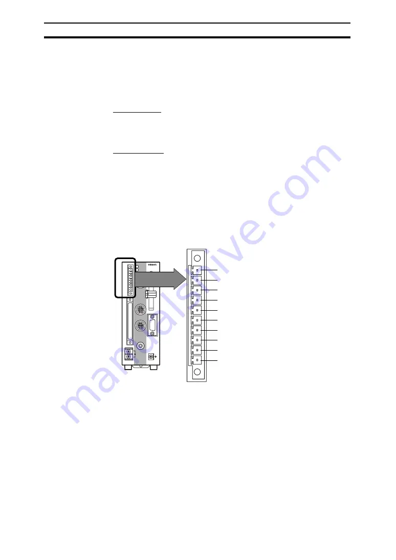
I/O Terminal Connections

Wire the cable carrying the control signals to the connector that was included
with the F160 and insert the connector into the F160. The following diagram
shows the I/O allocation of the F160's I/O terminals. Just wire the terminals
that are needed.

Note

1.

COMOUT is connected to COMOUT1 and COMOUT3 of the I/O connec-
tor.

2.

Use wire of cross-sectional area 0.14 to 1.5 mm

2

 (AWG 24 to AWG 16)

with a cable length not exceeding 30 m.

Precaution

Do not input the RESET input immediately after turning ON the power. When
using RESET input to synchronize startup timing, wait at least 1 s after turning
ON the F160's power supply before turning ON the RESET signal.

CHECK

Use a DC power supply with countermeasures against high voltages (safe
extra low-voltage circuits on the secondary side) for the COMIN terminal. If the
system must meet UL standards, use a UL class II power supply.

CONSOLE

STEP

RESET

COMIN

RUN

ERROR

OR

BUSY

GATE

DO15

COMOUT

ERROR

F160

STEP

RESET

COMIN

RUN

BUSY

GATE

OR

DO15

COMOUT

ERROR

(Input: Measurement trigger signal)

(Input: Restarts the F160.)

(Common for input terminals)

(Output: ON for measurement mode)

(Output: ON when error occurred)

(Output: Combined judgement result)

(Output: ON while processing)

(Output: ON for set output time)

(Output: Measurement results)

(Common for output terminals)

(See note.)

Artisan Technology Group - Quality Instrumentation ... Guaranteed | (888) 88-SOURCE | www.artisantg.com

Summary of Contents for F160-2 - 2

Page 1: ...service in house repair center WE BUY USED EQUIPMENT Sell your excess underutilized and idle used equipment We also offer credit for buy backs and trade ins www artisantg com WeBuyEquipment REMOTE IN...

Page 2: ...Cat No Z170 E1 02E F160 2 Vision Sensor Manual 1 SETUP MANUAL Artisan Technology Group Quality Instrumentation Guaranteed 888 88 SOURCE www artisantg com...

Page 3: ...WERE PROPERLY HANDLED STORED INSTALLED AND MAINTAINED AND NOT SUBJECT TO CONTAMINATION ABUSE MISUSE OR INAPPROPRIATE MODIFICATION OR REPAIR SUITABILITY FOR USE THE PRODUCTS CONTAINED IN THIS DOCUMENT...

Page 4: ...when published ratings or features are changed or when significant construction changes are made However some specifications of the product may be changed without any notice When in doubt special mode...

Page 5: ...F160 2 Vision Sensor Manual 1 Setup Manual Revised August 2015 Artisan Technology Group Quality Instrumentation Guaranteed 888 88 SOURCE www artisantg com...

Page 6: ...Artisan Technology Group Quality Instrumentation Guaranteed 888 88 SOURCE www artisantg com...

Page 7: ...iv Artisan Technology Group Quality Instrumentation Guaranteed 888 88 SOURCE www artisantg com...

Page 8: ...v Artisan Technology Group Quality Instrumentation Guaranteed 888 88 SOURCE www artisantg com...

Page 9: ...nient opera tion of the product 1 2 3 1 Indicates lists of one sort or another such as procedures checklists etc Precaution Indicates information required to take full advantage of the functions and p...

Page 10: ...eral Devices 15 2 5 Overview of Available Cameras 16 2 6 Power Supply and Ground 18 SECTION 3 Lenses Lighting and Memory Cards 21 3 1 CCTV Lenses 22 3 2 Lighting 24 3 3 Memory Card 26 SECTION 4 Connec...

Page 11: ...Artisan Technology Group Quality Instrumentation Guaranteed 888 88 SOURCE www artisantg com...

Page 12: ...rect hardware errors that may occur with the F160 as well as information on maintenance and periodic inspections Manual Contents Cat No 1 Setup Manual Provides information on system hardware and insta...

Page 13: ...Artisan Technology Group Quality Instrumentation Guaranteed 888 88 SOURCE www artisantg com...

Page 14: ...ble application of the F160 Vision Sensor You must read this section and understand the information contained before attempting to set up or operate an F160 Vision Sensor 1 General Safety Precautions...

Page 15: ...he top of the F160 to cover the cooling vents This label prevents wire strands from falling into the F160 during wiring so it must not be removed until wiring is com pleted The label must be removed a...

Page 16: ...ts get very hot and can cause burns Caution If you suspect an error or malfunction stop using the F160 immediately turn OFF the power supply and consult your OMRON representative Note Dispose of the F...

Page 17: ...eo is that with characters on the monitor are readable the test is pass 3 TRACEABILITY INFORMATION Importer in EU Omron Europe B V Wegalaan 67 69 2132 JD Hoofddorp The Netherlands Manufacture Omron Co...

Page 18: ...and operating the F160 Vision Sensor 1 1 Installation Precautions 2 1 1 1 Controller Installation 2 1 1 2 Component Installation and Handling 3 1 2 Confirming Package Contents 5 1 3 Product Availabil...

Page 19: ...to 85 range 4 Presence of corrosive or flammable gases 5 Presence of dust salt or iron particles 6 Direct vibration or shock 7 Direct sunlight 8 Water oil or chemical fumes or spray Orientation of Con...

Page 20: ...the F160 within 200 mm of power cables 1 1 2 Component Installation and Handling OMRON Components Use a Camera Camera Cable and Console designed specifically for the F160 Connecting Cables Always turn...

Page 21: ...Stop the power supply to the Memory Card from the menu Turning OFF the Power Do not turn OFF the power while a message is being displayed indicating that processing is being performed Data in memory...

Page 22: ...onnector for I O Terminals Qty 1 Phoenix Contact model MC1 5 10 STF 3 5 4 Ferrite Core for F150 VM Monitor Cable Qty 1 5 Setup Manual this manual Qty 1 6 Conversational Menu Operation Manual Qty 1 7 E...

Page 23: ...f the products listed may not be available in some countries Please contact your nearest OMRON sales office by referring to the addresses pro vided at the back of this manual Artisan Technology Group...

Page 24: ...Rear Surface mounting 12 2 3 3 Side Surface mounting 14 2 3 4 Bottom Surface mounting 15 2 4 Connecting Peripheral Devices 15 2 4 1 Connecting a Console 16 2 4 2 Connecting a Monitor 16 2 4 3 Connect...

Page 25: ...RESET COMIN RUN ERROR OR BUSY GATE DO15 COMOUT ERROR F160 PARALLEL MEMORY CARD Power Supply Recommended model OMRON S8VS 06024 F160 KP 2 m cable F150 KP 2 m cable Color LCD Monitor F150 M05L POWER SY...

Page 26: ...the Camera by itself when the field of vision of the Camera with Intelligent Light does not match the size of the measurement object A standard CCTV lens and light source will be needed Two different...

Page 27: ...personal computer or PLC 11 This lock secures the Memory Card so that it does not disconnect uninten tionally from vibration 12 Covers the compartment that contains the F160 s battery 13 This slot re...

Page 28: ...rface mounting or bottom surface mounting 2 3 1 DIN Track Mounting The Vision Mate Controller can be easily mounted to or removed from 35 mm DIN Track The following DIN Tracks are available from OMRON...

Page 29: ...ounting 1 Attach the mounting bracket to the F160 Controller using the four machine screws M3 6 included with the bracket STEP POWER RUN ERROR RESET COM IN RUN ERR OR BUSY GATE OR DO15 PARALLEL COMOUT...

Page 30: ...oles and dimensions shown in the following diagram STEP POWER RUN ERROR RESET COM IN RUN ERR OR BUSY GATE OR DO15 PARALLEL COMOUT CONSOLE CAMERA 0 MONITOR 24VDC RS 232C 422 CAMERA 1 F160 VISION MATE C...

Page 31: ...nd dimensions shown in the following diagram STEP POWER RUN ERROR RESET COM IN RUN ERR OR BUSY GATE OR DO15 PARALLEL COMOUT CONSOLE CAMERA 0 MONITOR 24VDC RS 232C 422 CAMERA 1 F160 VISION MATE CONTROL...

Page 32: ...evice may be damaged if it is con nected while the power is ON At the time of delivery a cap is mounted to all of the connectors To prevent the penetration of dust and dirt and to protect against stat...

Page 33: ...ote The connector is capped when the F160 is shipped When not using the con nector leave the cap in place to protect against dust dirt and static electricity 2 5 Overview of Available Cameras The F160...

Page 34: ...mm Mounting distance 15 to 25 mm 16 5 to 26 5 mm Relationship between Camera and object Lighting precautions Use with DIP switch pins 1 and 2 both set to OFF Use with DIP switch pins 1 and 2 both set...

Page 35: ...ive terminals Tighten the screws to a torque of between 0 49 N m After wiring confirm that the wiring is correct 2 6 1 Crimp Terminals and Cables The terminal block uses M3 terminal screws Use appropr...

Page 36: ...ications We recommend using OMRON s S8VS 06024 Power Supply CHECK Use a DC power supply with countermeasures against high voltages safe extra low voltage circuits on the secondary side If the system m...

Page 37: ...Artisan Technology Group Quality Instrumentation Guaranteed 888 88 SOURCE www artisantg com...

Page 38: ...1 1 Optical Chart 22 3 1 2 Lenses and Lens Diameters 23 3 1 3 Extension Tubes 24 3 2 Lighting 24 3 2 1 Lighting Methods 24 3 3 Memory Card 26 3 3 1 Installing a Memory Card 27 3 3 2 Removing the Memor...

Page 39: ...the thickness of the extension tube used t0 is used if an extension tube is not necessary and t5 0 is used if a 5 mm extension tube is used Example If you use a 3Z4S LE SV 2514V CCTV Lens for a measu...

Page 40: ...P0 5 3Z4S LE SV 1214V 12 43 mm F1 4 29 mm 29 5 mm M27 P0 5 3Z4S LE SV 1614V 16 34 mm F1 4 29 mm 24 0 mm M27 P0 5 3Z4S LE SV 2514V 25 17 mm F1 4 29 mm 24 5 mm M27 P0 5 3Z4S LE SV 3518V 34 75 mm F1 8 2...

Page 41: ...d together Reinforcement may be required for combinations of Extension Tubes exceeding 30 mm if the Camera is subject to vibration 3 2 Lighting A stable image must be obtained to ensure accurate inspe...

Page 42: ...iformly on the measurement object Applications Surface inspections Oblique Lighting Detection can be made utilizing the difference in regular and diffuse reflected light Light source Measurement objec...

Page 43: ...can be backed up in a personal computer just by inserting the Memory Card into the computer and copying the desired data We recommend the OMRON F160 N256S 256 MB Memory Card CHECK A filler card with n...

Page 44: ...Stop the power supply to the Memory Card or turn OFF the F160 SeeAlso Refer to the Conversational Menu Operation Manual or the Expert Menu Operation Manual for details on turning OFF the power supply...

Page 45: ...lot 3 3 3 Using Memory Cards in a Personal Computer The F160 s Memory Cards can be used in a personal computer with a PC Card drive PCMCIA 2 0 or higher type II compatible or Compact Flash drive The M...

Page 46: ...2C RS 422 connector 4 1 Connecting through the Parallel Interface 30 4 1 1 I O Terminal Connections 30 4 1 2 I O Connector Connections 31 4 1 3 I O Specifications 33 4 2 Connecting through the Serial...

Page 47: ...o the F160 The following diagram shows the I O allocation of the F160 s I O terminals Just wire the terminals that are needed Note 1 COMOUT is connected to COMOUT1 and COMOUT3 of the I O connec tor 2...

Page 48: ...of 0 22 to 0 25 N m 4 Insert the connector into the F160 5 Tighten the connector s mounting screws Tighten to a torque of 0 22 to 0 25 N m 4 1 2 I O Connector Connections Use an F160 VP Parallel I O C...

Page 49: ...ght brown black Restarts the F160 A2 STEP Yellow black Measurement trigger signal input A3 DI0 Green black Command input A4 DI2 Gray black A5 DI4 White black A6 DI6 Light brown black A7 DI8 Yellow bla...

Page 50: ...onnector wiring for mistakes before turning ON the power supply for the first time 4 1 3 I O Specifications Input Specifications B8 STGOUT1 Green red Strobe trigger 1 output See note 1 B9 ERROR Gray r...

Page 51: ...60 s serial interface RS 232C RS 422 connector can be used to con nect input signals such as measurement triggers or output signals such as measurement results Additionally data that has been set in t...

Page 52: ...s is possible using Link Adapters 1 1 Connection Host Link Computer F160 RS 232C cable Computer Link Adapter F160 RS 232C cable RS 422 cable RS 422 cable RS 422 cable Link Adapter Link Adapter F160 Li...

Page 53: ...able length is 15 m for RS 232C or RS 422 RS 232C Wiring Pin Signal Name 1 FG Protective frame ground 2 SD For RS 232C 3 RD 4 NC Not connected 5 RDB For RS 422 6 RDA 7 SDB 8 SDA 9 GND Signal ground Mo...

Page 54: ...he connector Precaution Always turn OFF the power supply before connecting or disconnecting cables The peripheral device may be damaged if connected or discon nected with the power supply turned ON Th...

Page 55: ...Artisan Technology Group Quality Instrumentation Guaranteed 888 88 SOURCE www artisantg com...

Page 56: ...g 40 5 1 1 Connection Errors 40 5 1 2 Menu Operation Errors 40 5 1 3 Parallel Interface Errors 40 5 1 4 Serial Interface Errors 41 5 2 FAQ 41 5 2 1 Cameras 41 5 2 2 Cables 42 5 3 Maintenance 42 5 3 1...

Page 57: ...The Camera Cable is not properly connected The lens iris is opened or closed too far The shutter speed is not suitable The lighting method is not suitable The indicators do not turn ON for Cameras wit...

Page 58: ...d is the timing of the shutter trigger pulse synchronized F160 S2 F150 S1 The timing is not synchronized In order to prevent light interference from other Cameras the timing is staggered by a displace...

Page 59: ...in the camera base 3 Remove the two screws securing the Light 4 Remove the Light from the Camera 5 Reverse steps 1 through 4 when installing the Lens and Light Precaution Do not disassemble the Lens D...

Page 60: ...he bottom of the Camera instead of the long screws removed in step 4 The screws removed in step 3 are not needed 5 3 2 Replacing the Battery The F160 contains a battery that backs up the time and date...

Page 61: ...n perform the following regularly Clean the Lens and LED indicators with a lens cleaning wipe or blow off dust with an aerosol air sprayer Lightly wipe off dirt with a soft cloth STEP POWER RUN ERROR...

Page 62: ...st be firmly secured Each cable connector must be correctly inserted and locked The Cameras must be firmly secured The camera lens mounts must be firmly secured Phillips screwdriver Indicators All ind...

Page 63: ...continuation time 15 ms Period 300 ms Vibration resistance 10 to 150 Hz half amplitude 0 35 mm maximum acceleration 50 m s2 10 times for 8 minutes each in 3 directions except for bottom surface mount...

Page 64: ...with Light F150 SL20A SL50A 67 F150 LT10A Light 3 8 dia 27 39 70 5 43 1 25 4 Unit mm 20 0 1 40 25 16 75 50 25 6 75 Two M4 taps Depth 8 1 4 20UNC tap Depth 8 Artisan Technology Group Quality Instrumen...

Page 65: ...F150 SLC20 85 70 70 2 5 2 5 12 42 5 73 40 10 25 12 40 31 12 12 30 5 Unit mm 4 dia F150 LTC20 Light 6 75 Two M4 taps Depth 10 1 4 20UNC tap Depth 10 86 25 96 25 20 0 1 16 75 Artisan Technology Group Qu...

Page 66: ...16 16 16 16 60 31 2 5 2 5 90 90 40 85 Unit mm 10 25 4 dia 30 5 F150 LTC50 Light 6 75 Two M4 taps Depth 10 1 4 20UNC tap Depth 10 20 0 3 16 75 93 25 103 25 Artisan Technology Group Quality Instrumenta...

Page 67: ...30 5 1 5 Camera Cable Connector 11 8 dia Light Connector 8 8 dia 31 30 7 21 7 Unit mm 20 0 1 21 25 2 31 25 2 6 2 6 2 29 11 15 5 14 5 16 75 6 75 Two M4 taps Depth 8 1 4 20UNC tap Depth 8 Artisan Techn...

Page 68: ...ing F160 SLC20 70 70 2 5 2 5 12 42 5 73 46 5 12 40 31 12 12 23 25 13 25 20 0 3 86 25 96 25 30 5 8 Two M4 taps Depth 10 1 4 20UNC tap Depth 10 Unit mm 85 10 25 4 dia F150 LTC20 Light Artisan Technology...

Page 69: ...25 20 0 3 Two M4 taps Depth 10 1 4 20UNC tap Depth 10 85 25 8 54 5 6 46 5 1 32UN 2A C mount 15 5 30 5 8 Camera Cable Connector 11 8 dia Light Connector 8 8 dia 29 11 14 5 31 30 7 21 7 Unit mm 20 0 1 2...

Page 70: ...amera materials Cover Galvanized steel sheet metal Case Die cast aluminum alloy Camera mounting base Fiber reinforced plastic black Light materials Cameras with Lights Case ABS Transparent cover PC We...

Page 71: ...0 SLC20 SLC50 Red and green LED combination Peak emission wavelengths 660 nm and 570 nm Light emission method Pulse emission synchronized with the camera shutter Item Specification Mounting distance F...

Page 72: ...n Storage 25 to 65 C with no condensation Ambient humidity range 35 to 85 with no condensation Ambient environment No corrosive gases Degree of protection IEC60529 IP20 in panel Minimum bending radius...

Page 73: ...50 m s2 10 times for 8 minutes each in 3 directions Shock resistance 150 m s2 3 times each in 6 directions Ambient temperature range Operating 0 to 50 C with no condensation Storage 25 to 65 C with n...

Page 74: ...ch is set to DISABLE ENABLE DISABLEE ENABLE Item Specification Vibration resistance 10 to 150 Hz half amplitude 0 15 mm 4 times for 8 minutes each in 3 directions Shock resistance 196 m s2 3 times eac...

Page 75: ...12 1 2 3 4 5 6 7 8 9 10 11 12 Pin F160 Connector Signal Connector model Hirose HR10A 10P 12SC 73 Connector model Hirose RP17A 13PA 12PC 71 Item Specification Vibration resistance 10 to 150 Hz half am...

Page 76: ...imes for 8 minutes each in 3 directions Shock resistance 196 m s2 3 times each in 6 directions Ambient temperature range Operating 0 to 50 C with no condensation Storage 25 to 65 C with no condensatio...

Page 77: ...in panel Materials Case ABS PC Display surface PMMA Acrylic Panel size 5 7 inches Panel type TFT color liquid crystal Resolution 640 480 dots Image pitch 0 1815 0 1815 mm H V Contrast 850 1 typical V...

Page 78: ...ngs Detail Menu The Camera settings Detail window is displayed at startup and can be dis played at other times by selecting Camera settings from the System Menu Weight Approx 1 kg Accessories Four mou...

Page 79: ...ter trigger polarity Shutter trigger width STGOUT0 or STGOUT1 signal when the flash is synchronized to the OFF to ON tran sition of the strobe trigger signal Positive The shutter trigger width setting...

Page 80: ...DIN Track 11 E Extension Tubes 24 external devices connecting 29 F F150 Cameras dimensions 47 F150 KP 55 F150 M05L 60 F150 S1A 50 F150 SL20A SL50A 42 47 F150 SLC20 48 F150 SLC20 SLC50 43 F150 SLC50 4...

Page 81: ...18 turning OFF 4 wiring 19 precautions xi applications xiii battery xii general safety xii installation 2 installation environment xii power supply and wiring xii products availability 6 R RESET signa...

Page 82: ...temperature and Ambient humidity changed to Ambient temperature range and Ambi ent humidity range respectively Page 59 Information on F160 VSR3 Camera Cable removed Page 60 Information on F160 VSR4 C...

Page 83: ...Artisan Technology Group Quality Instrumentation Guaranteed 888 88 SOURCE www artisantg com...

Page 84: ...Artisan Technology Group Quality Instrumentation Guaranteed 888 88 SOURCE www artisantg com...

Page 85: ...43 7787 Regional Headquarters OMRON EUROPE B V Wegalaan 67 69 2132 JD Hoofddorp The Netherlands Tel 31 2356 81 300 Fax 31 2356 81 388 Contact www ia omron com Kyoto JAPAN OMRON ASIA PACIFIC PTE LTD No...

Page 86: ...service in house repair center WE BUY USED EQUIPMENT Sell your excess underutilized and idle used equipment We also offer credit for buy backs and trade ins www artisantg com WeBuyEquipment REMOTE IN...

Reviews: