25
F250
Setup Manual
SECTION 2
Installation and Connections
SECTION 2
Co
nn
ec
tin
g
Periph
er
al De
vic
es
Connecting Peripheral Devices
This section shows how to connect peripheral devices to the Controller.
Always turn OFF the power supply before connecting or disconnecting a peripheral device's cable.The
peripheral device may be damaged if it is connected while the power is ON.
The various connectors on the Controller are capped when the Controller is shipped. When a connector is
not being used, leave the cap in place or replace the cap to protect against dust, dirt, and static electricity.
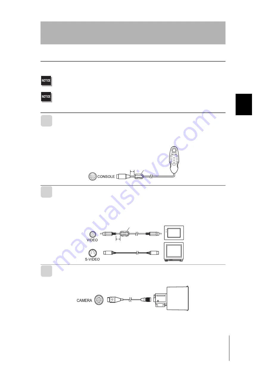
Connecting a Console
Connect the Console to the Controller's CONSOLE connector.An F160-KP or F150-KP Console
can be connected.Install the provided ferrite core (*) onto the cable, positioning the ferrite core
about 10 mm from the Controoler-side connector.
Connecting a Monitor
Connect the monitor cable to the Controller's MONITOR connector.Install the provided ferrite
core onto the F150-VM Monitor Cable, positioning the ferrite core (*) about 10 mm from the
Controller-side connector.
The S-VIDEO and VIDEO outputs can be used simultaneously.
Connecting a Camera
Connect the camera cable to the Controller's Camera connector.
* The ferrite core is supplied only with models that support CE. It is not necessary to install it in
models that do not support CE. Please contact any of our branches or sales offices for further
details.
5*+(6
'06
64+)
'5%
Ferrite core
Approx. 10 mm
219'4
5;0%
Ferrite core
Approx. 10 mm


