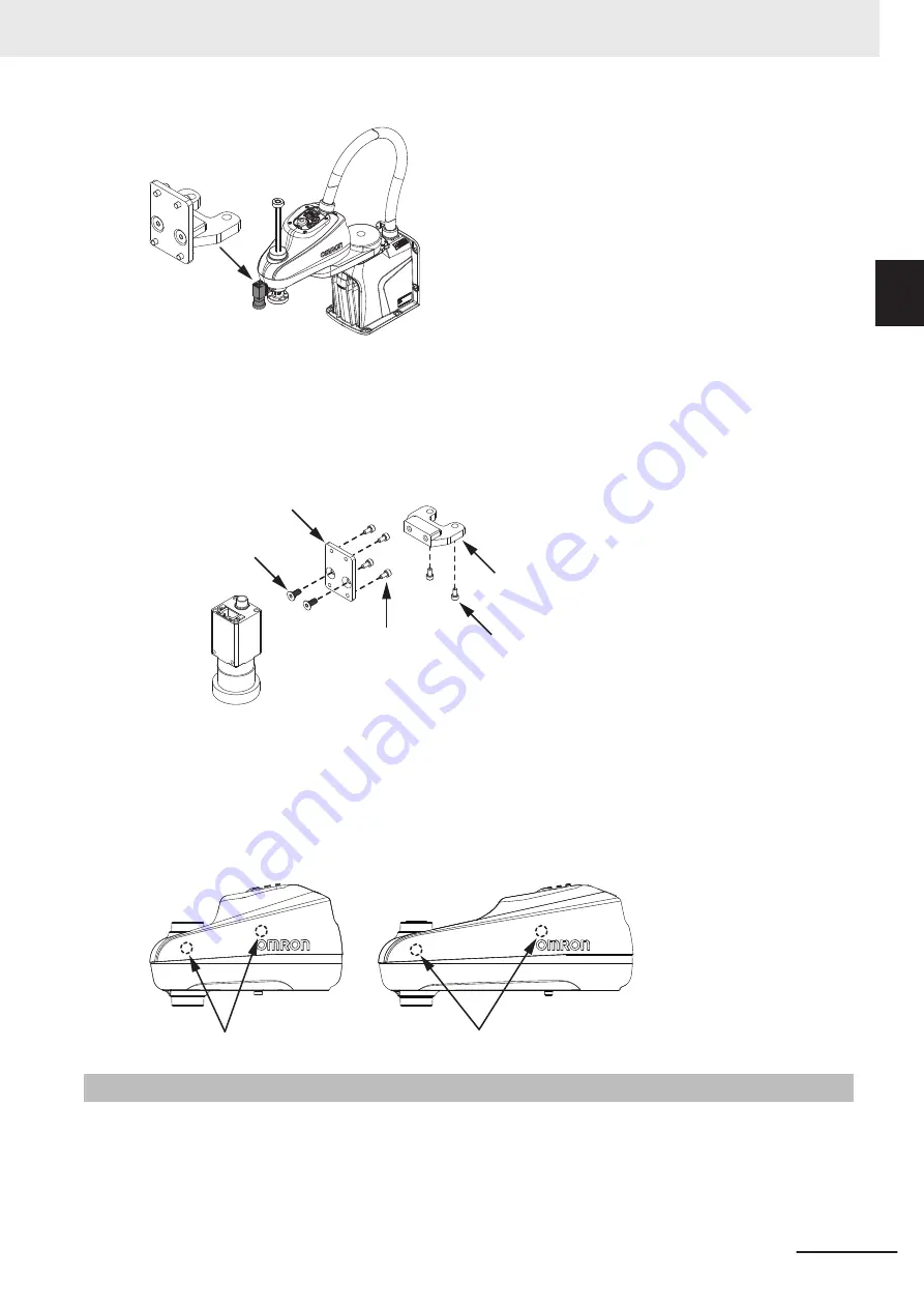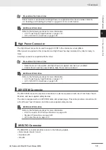
Apply Loctite 222 or equivalent thread locking compound to all screws. Apply the following torque val-
ues when tightening the screws.
• 51120-67010: 2.9 N-m
• 04221001184-0006: 1.3 N-m
• 51006-69012: 5.7 N-m
22866-000
22866-100
51120-67010 (2)
04221001184-0006 (4)
51006-69012 (2)
The following items are included in the camera mounting bracket kit for cable management.
• 23681-000 (2)
• 27300-00024 (4)
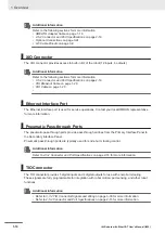
Item 23681-000 can be installed for cable management. Remove the outer link cover, drill 0.25 inch
holes in the locations shown below, and then insert the cable tie mounts. Refer to
Valve Kit Installation Procedure
on page 3-15 for more information about outer link cover removal
and replacement.
1-6-7
Bellows Kit
Bellows are an optional item that can be placed on upper and lower exposed portions of the Joint 3
quill for additional environmental protection. Bellows prevent debris or liquid from entering the internal
compartment of the outer link, protect the Joint 3 quill, and prevent contamination of items external to
the robot.
1 Overview
1-21
i4L Robots with EtherCAT User's Manual (I659)
1-6 Optional Hardware
1
1-6-7
Bellows Kit
Summary of Contents for i4-350L
Page 1: ...i4L Robots with EtherCAT User s Manual i4 350L i4 450L i4 550L I659 E 01...
Page 6: ...Manual Information 4 i4L Robots with EtherCAT User s Manual I659...
Page 54: ...1 Overview 1 26 i4L Robots with EtherCAT User s Manual I659...
Page 72: ...2 Specifications 2 18 i4L Robots with EtherCAT User s Manual I659...
Page 122: ...3 Installation 3 50 i4L Robots with EtherCAT User s Manual I659...
Page 138: ...4 Operation 4 16 i4L Robots with EtherCAT User s Manual I659...
Page 169: ...I Index I 1 i4L Robots with EtherCAT User s Manual I659 I...
Page 172: ...Index I 4 i4L Robots with EtherCAT User s Manual I659...
Page 173: ......


