Chapter 6: Maintenance
remove the top U-joint, which is attached to the J4 motor shaft.
3. Attach one pair of outer arms to each of the three pairs of ball studs on the new plat-
form.
l
The platform must be installed with the tool flange in the downward orientation.
l
Take care not to trap debris between the ball studs and their sockets.
4. For a 4 axis robot, attach the theta drive shaft to the platform drive shaft.
Refer to Installing the Platform on page 37 for details.
6.13 Replacing a Ball Joint Socket Insert
Use the following procedure to replace a ball joint socket insert.
1. Remove the outer arm from the ball joint. This does not require any tool and can be
accomplished by hand.
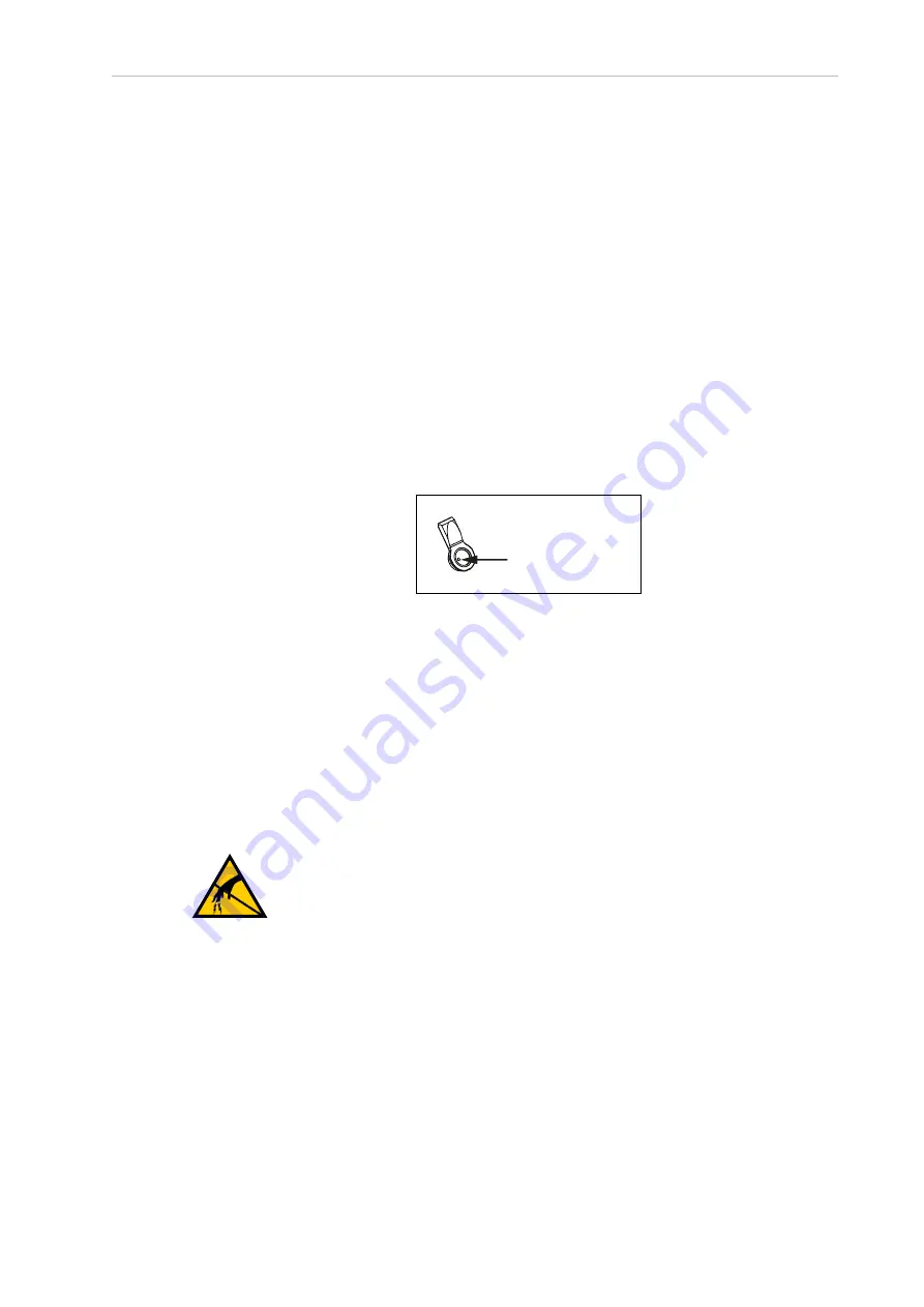
2. The inserts have a threaded hole to facilitate removal. To extract the old insert, use an
M4 bolt to thread into the insert and then pull it out.
Extraction Hole
3. To install the new insert, press it into place by hand ensuring that it is centered and
fully seated.
4. After the insert is in place, install the outer arm on the ball joint.
5. Repeat steps 1 through 4 for all ball joint socket inserts that need to be replaced to com-
plete this procedure.
6.14 Replacing the iCS-ECAT Unit
Use the following procedure to replace the iCS-ECAT unit.
Record all faults or errors and switch positions before beginning this procedure.
CAUTION:
PROPERTY DAMAGE RISK
Follow appropriate ESD procedures during the removal and replacement
phases.
1. Remove all power from the robot.
2. Disconnect the 24 VDC supply cable from the c24 VDC input connector.
3. Disconnect the 200 to 240 VAC supply cable from the chassis AC Input connector.
4. Disconnect the XSYSTEM cable from the chassis XSYSTEM connector.
5. Disconnect any other cables that may be connected to the iCS-ECAT.
22792-000 Rev. A
iX3 565 Robot with EtherCAT User’s Manual
113


