Chapter 3: Robot Installation
Figure 3-8. Springs Seated Properly
After all outer arms are fastened to both the inner arms and platform, the platform
installation procedure is complete.
3.5 Installing the Front Panel
Use the information provided in this section to install the Front Panel.
When mounting the Front Panel, you must select an installation location outside the robot's
workcell where it can immediately be reached in an emergency.
Possible mounting locations include immediately next to the workcell gate, on a nearby desk,
or other readily accessible location.
!
DANGER:
A remote High Power push-button must be installed outside of the
robot's workspace.
Mounting the Front Panel
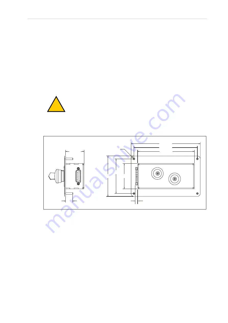
Use dimensions provided in the figure below when mounting the Front Panel.
56 mm
76 mm
89 mm
125 mm
152 mm
140 mm
41 mm
16 mm
Ø 4 mm
5 mm
Figure 3-9. Front Panel Dimensions
Connecting the Front Panel
The Front Panel is connected to the XFP connector on the XSYSTEM cable using the supplied
Front Panel extension cable.
22792-000 Rev. A
iX3 565 Robot with EtherCAT User’s Manual
41


