Chapter 3: Robot Installation
ESTOPSRC
24 VS
5 VD
D
SYSPWRLT
7
6
5
4
2
3
1
17
16
8
10
9
11
12
13
14
15
XFP
15PDSUBM
MANUALSRC1
HIPWRREQ
MANUALRLY2
MANUALRLY1
HIPWRLT
ESTOPFP2
ESTOPFP1
HPLT5V
NC
MANUALSRC2
MANUALSRC1
SW1
MANUALRLY2
MANUALRLY1
MANUALSRC2
24 VS
SWL1
HIPWRREQ
HPLT5 V
HIPWRLT
D
ESTOPSRC
SW2
ESTOPFP2
ESTOPFP1
5 VD
D
2-PIN_MINI
SYSPWRLT
System Power
LED
Manual / Automatic
Switch
High Power
Indicator / Buon
Emergency
Stop
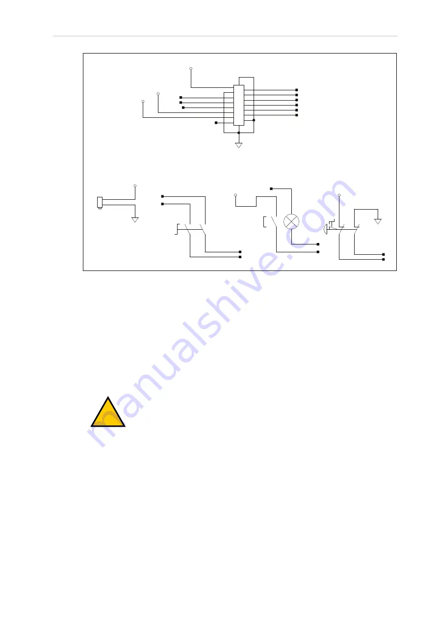
Figure 3-11. Front Panel Schematic
IMPORTANT:
Disabling the High Power button violates IEC 60204-1. We
strongly recommend that you not alter the use of the High Power button.
3.6 Installing User-Supplied Safety Equipment
You are responsible for properly installing safety equipment to protect personnel from unin-
tentionally coming in contact with the robot. Depending on the design of the workcell, you can
use safety gates, light curtains, emergency stop devices, and other safety equipment to create a
safe environment.
!
WARNING:
Installing, commissioning, or operation of any robot without
adequate safety equipment is strictly prohibited. This equipment must be com-
pliant with all applicable and local standards. Failure to install suitable safety
equipment could result in injury or death.
Additional Information
: Refer to the
Robot Safety Guide (Cat. No. I590)
for more
information.
The user-supplied safety and power-control equipment connects to the system through the
XUSR and XFP connectors on the XSYSTEM cable. The XUSR connector (25-pin) and XFP (15-
pin) connector are both female D-sub connectors. Refer to the following sections for safety
equipment connection details.
22792-000 Rev. A
iX3 565 Robot with EtherCAT User’s Manual
43


