K8AK-VW
6
Operation and Setting Methods
●
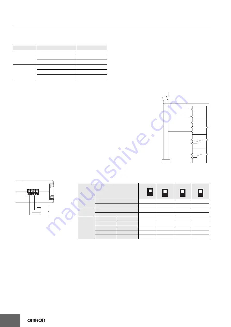
Setting Ranges and Wiring Connections
●
Connections
1.
Input
Connect the input between terminals V1-COM, V2-COM, or V3-COM, depending on the input
voltage.
Malfunctions may occur if the input is connected to unused terminals and the Unit will not operate
correctly.
2.
Power Supply
Connect the power supply to terminals A1 and A2.
3.
Outputs
AL1 (SPDT relay) is output to terminals 11, 12, and 14.
AL2 (SPDT relay) is output to terminals 21, 22, and 24.
Note:
Use the recommended ferrules if using twisted wires.
●
DIP Switch Settings
The power ON lock time, resetting method and operating mode are set using the DIP switch located on the bottom of the Unit.
●
Setting Method
1.
Setting Voltage
The voltage knob (AL1 and AL2) is used to set the voltage.
The voltage can be set to 10% to 100% of the maximum setting range.
Turn the knob while there is an input to the input terminals until the alarm indicator flashes (when the set value and the input have reached the
same level.)
Use this as a guide to set the voltage.
The maximum setting range will differ depending on the model and the input terminal.
Example: K8AK-VW3 Using Input Terminal V3-COM
The maximum setting range will be 600 VAC/VDC and the setting range will be 60 to 600 V.
2.
Operating Time
The operating time is set using the operating time knob (T).
The operating time can be set to between 0.1 and 30 s.
Turn the knob while there is an input to the input terminals until the alarm indicator flashes (when the set value and the input have reached the
same level.)
Use this as a guide to set the operating time.
If the input exceeds (or drops lower than) the voltage set value, the alarm indicator will start flashing for the set period and then stay lit.
Model
Setting range
Wiring connection
K8AK-VW2
1 to 10 V AC/DC
V1-COM
3 to 30 V AC/DC
V2-COM
15 to 150 V AC/DC
V3-COM
K8AK-VW3
20 to 200 V AC/DC
V1-COM
30 to 300 V AC/DC
V2-COM
60 to 600 V AC/DC
V3-COM
Load
Power supply
voltage
Voltage input
Signal output
Signal output
14
24
12
22
A1
A2
V1
V2
V3
11
21
AL1 relay
signal
output
AL2 relay
signal
output
C (COM)
Single-phase power
SW3
DIP switch pins
ON
OFF
SW2
SW1
SW4
DIP Switch Functions
Note:
All pins are set to OFF at the factory.
Pin
OFF
●
↑
ON
❍
↓
Power ON
lock time
1 s
●
---
---
---
5 s
❍
---
---
---
Resetting
method
Manual reset
---
●
---
---
Operating mode
---
❍
---
---
Operating
mode
AL1
AL2
Overvoltage
Undervoltage
---
---
●
●
Overvoltage
Overvoltage
---
---
❍
●
Undervoltage
Undervoltage
---
---
●
❍
Overvoltage
Undervoltage
---
---
❍
❍
1
OFF
ON
2
3
4


