K8DT-PZ
11
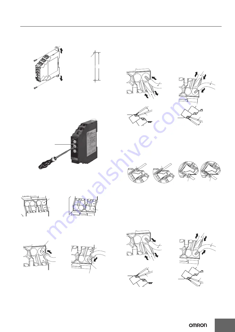
Screw Mounting
1.
Pull out the two hooks on the back of the Relay to the outside until
you hear them click in place.
2.
Insert M3 screws into the hook holes and secure the Relay.
Adjusting the Setting Knobs
• Use a flat-blade screwdriver to adjust the setting knobs. The knobs
have a stopper that prevents them from turning beyond the full right
or left position. Do not force a knob beyond these points.
• To reduce the error in the setting knob, always turn the setting knob
from the minimum setting toward the maximum setting.
Connecting Wires to the Push-In Plus Terminal Block
Part Names of the Terminal Block
Connecting Wires with Ferrules and Solid Wires
Insert the solid wire or ferrule straight into the terminal block until the
end strikes the terminal block.
If a wire is difficult to connect because it is too thin, use a flat-blade
screwdriver in the same way as when connecting stranded wire.
Connecting Stranded Wires
Use the following procedure to connect the wires to the terminal block.
1.
Hold a flat-blade screwdriver at an angle and insert it into the
release hole. The angle should be between 10° and 15°.
If the flat-blade screwdriver is inserted correctly, you will feel the
spring in the release hole respond.
2.
With the screwdriver still inserted into the release hole, insert the
wire into the terminal hole until it strikes the terminal block.
3.
Remove the flat-blade screwdriver from the release hole.
Checking Connections
• After the insertion, pull gently on the wire to make sure that it will
not come off and the wire is securely fastened to the terminal block.
• To prevent short circuits, insert the stripped part of a stranded or
solid wire or the conductor part of a ferrule until it is hidden inside
the terminal insertion hole. (See the following diagram.)
Removing Wires from the Push-In Plus Terminal Block
Use the following procedure to remove wires from the terminal block.
The same method is used to remove stranded wires, solid wires, and
ferrules.
1.
Hold a flat-blade screwdriver at an angle and insert it into the
release hole.
2.
With the flat-blade screwdriver still inserted into the release hole,
remove the wire from the terminal insertion hole.
3.
Remove the flat-blade screwdriver from the release hole.
(1)
(1)
(2)
(2)
Two M3 screw holes or
two 3-dia. holes
108
Mounting Hole Dimensions
Note: 1.
Pull out the hooks to mount
the Relay with screws.
2.
Recommended tightening
torque: 0.5 to 0.6 N·m.
Setting knob
Release hole
Terminal
(Insertion) hole
Release hole
Terminal
(Insertion) hole
<Upper side>
<Lower side>
Ferrule
Release hole
Terminal
(Insertion) hole
Ferrule
Release hole
Terminal
(Insertion) hole
<Upper side>
<Lower side>
Wire
Flat-blade screwdriver
(1)
(3)
(2)
Wire
Flat-blade screwdriver
(1)
(2)
(3)
10 to 15°
10 to 15°
Flat-blade
screwdriver
Flat-blade
screwdriver
<Upper side>
<Lower side>
Ferrule
Ferrule
<Upper side>
<Lower side>
Wire
<Lower side>
Wire
<Upper side>
Wire
Flat-blade screwdriver
(1)
(3)
(2)
Wire
Flat-blade screwdriver
(1)
(2)
(3)
10 to 15°
10 to 15°
Flat-blade
screwdriver
Flat-blade
screwdriver
<Upper side>
<Lower side>


