21
Installation
Section 2-2
• Power supply
Applicable power supply specifications are as follows.
• Parts used for connection
Use crimp terminals to connect the power supply to the power input termi-
nals. Recommended crimp terminals for M3.5 are given below.
!Caution
For the connection to the power supply terminal block, twisted wires of 2 mm
2
or greater cross sectional area and M 3.5 size crimp terminals must be used.
Tighten the screws on the terminal block to a torque of 0.5 N
×
m.
Otherwise fire may occur.
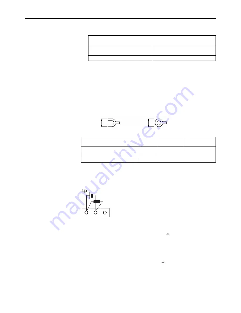
[Recommended terminals]
Note
When surge noise occurs in the DC power supply, connect a Transistor Volt-
age Suppressor (TVS) between the 24-V and 0-VDC terminals.
Recommended TVS model: 1.5KE33CA
Manufacturers: Vishay Intertechnology Inc, STMicroelectronics
2-2-3
Wiring the Ground Wire
The PT is provided with a functional ground (FG:
) terminal.
Wire the FG terminal according to the following conditions.
1.
Ground according to Figure when there is difference in potential between
the PT and host. Do not ground the functional ground of the PT if it is far
from the host and one-point grounding is difficult.
2.
Do not ground the functional ground (FG:
) of the PT if it is mounted to
the same panel as devices that generate noise, such as motors and invert-
ers.
Item
Value
Power supply voltage
24 VDC
Allowable power supply voltage
fluctuation range
20.4 VDC to 26.4 VDC
(24 VDC –15%, +15%)
Power supply capacity
10 W or lower
Maker
Type
(fork type)
Type
(round type)
Applicable Wire
(stranded wire)
Japan Solderless Terminal MFG
2-YS3A
2-3.5
1.04 to 2.63 mm
2
Fuji Terminal
2-YAS3.5
V2-S3.5
Nichifu Terminal
2Y-3.5
2-3.5
Fork type
Round type
7 mm or less
7 mm or less
24 VDC
TVS
Summary of Contents for NT11 - 01-2004
Page 1: ...USER S MANUAL Cat No V084 E1 01 NT11 Programmable Terminal ...
Page 2: ...NT11 Programmable Terminal User s Manual Produced January 2004 ...
Page 3: ...iv ...
Page 5: ...vi ...
Page 13: ...xiv Safety Precautions 3 ...
Page 27: ...14 Before Operating Section 1 6 ...
Page 71: ...58 Connecting a Printer Section 2 8 ...
Page 119: ...106 Daily Report Display History Printing Function Section 4 10 ...
Page 157: ...144 Inspection and Cleaning Section 6 3 ...
Page 162: ...149 Appendix B Dimensions Body NT11 SF121 B EV1 38 2 7 5 218 203 113 98 ...
Page 163: ...150 Dimensions Appendix B ...
Page 165: ...152 Transporting and Storing the NT11 Appendix C ...
Page 183: ...170 Revision History ...
Page 186: ...NT11 Programmable Terminal Cat No V084 E1 01 USER S MANUAL ...


