98
Connecting to the Host’s RS-232C Port
Section 5-1
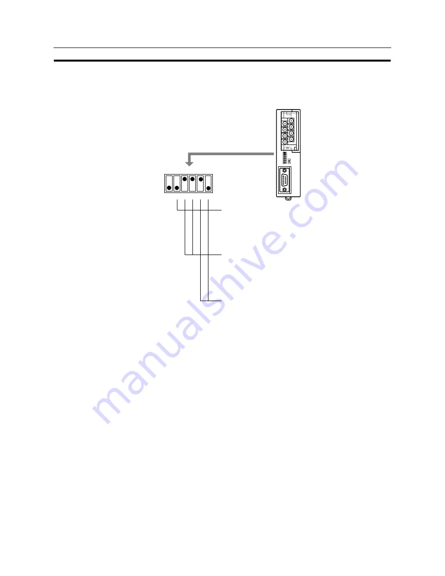
Settings at the RS-232C/RS-422A Convertor Unit (NT-AL001)
When making a connection between RS-232C and RS-422A/485 ports using an
RS-232C/RS-422A convertor unit, set the DIP switches on the NT-AL001 as fol-
lows.
1
2
3
4
5
6
ON
om on
R
NT-AL001
Built-in terminal resistor setting (DIP SW1-2)
If at the end of the RS-422A/485 cable, set this switch to ON (to
activate the built-in terminal resistor).
If not at the end of the RS-422A/485 cable, set this switch to OFF
(to inactivate the built-in terminal resistor).
2-wire type/4-wire type selection (DIP SW1-3, SW1-4)
For RS-422A, set both of these switches to OFF (4-wire type).
For RS-485, set both of these switches to ON (2-wire type).
Selection of RS-422A/485 send mode (DIP SW1-5, SW1-6)
For host link or NT link (1:1), set both of these switches to OFF.
(Always send)
For NT link (1:N), set SW1-5 to OFF and SW1-6 to ON.
(Sends when CS is “H”)
Example: the terminal resistor is active,
RS-422A, NT link (1:N).
Note
Read the manual supplied with the NT-AL001 carefully before using the unit.
Summary of Contents for NT31 Series
Page 1: ...Cat No V043 E1 2 Programmable Terminal NT31 31C OPERATION MANUAL...
Page 2: ...iii NT31 31C Programmable Terminal Operation Manual Produced March 1999...
Page 41: ...30 Before Operating Section 1 5...
Page 75: ...64 Using a Memory Unit NT31 NT31C without V1 Section 3 6...
Page 160: ...149...
Page 174: ...163...
Page 193: ...182...
Page 211: ...200...
Page 235: ...224 c Return to the screen on which screens are specified...
Page 262: ...251...
Page 360: ...349 It is not possible to control a gloval window by touch switch operation...
Page 468: ...457 254 255 0 2 7 1 4 5 3 3 0 0 0 5 9 8 0 3...
Page 476: ...465 Special Functions Section 7 16...
Page 495: ...484 OFF...
Page 610: ...599 Commands Responses Section 9 3...
Page 630: ...619 Examples of Actual Applications of Memory Link Section 10 2...


